A hackspace discussion of voltage regulators within our earshot touched on the famous μA723, then moved on to its competitors. Kits-of-parts for linear regulators were ten-a-penny in the 1970s, it seems. A rambling tale ensued, involving a Lambda power supply with a blown-up chip, and ended up with a Google search for the unit in question. What it turned up was a hack from 2014 that somehow Hackaday missed at the time, the replication by [Eric Schlaepfer] of an out-of-production regulator chip using surface-mount semiconductors when his Lambda PSU expired.
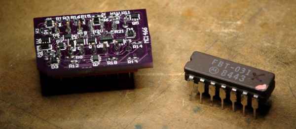
Lambda were one of those annoying electronics companies with a habit of applying their own part numbers to commonly available chips in an effort to preserve their spares sales. Thus the FBT-031 in this Lambda PSU was in fact a Motorola MC1466, a dirt-cheap common part in the 1970s. Unfortunately though unlike the 723 the MC1466 has long passed out of production, and is rarer than the proverbial hen’s tooth.
Happily, these chips from the early 1970s were often surprisingly simple inside. The MC1466 schematic can be found on its data sheet, and is straightforward enough to replicate with surface-mount discrete components. He thus created a PCB that replicated the original pin layout even though it overlapped the original footprint. A few parts were slightly unusual, dual transistor arrays and a matched triple diode, but the result proved to be a perfect replacement for a real MC1466. Of course a project like this is almost too simple for [Eric], who went on to build the incredible Monster 6502.
If the data sheet lacks a schematic, never fear. You can always try reverse engineering the chip directly.


 Data begin sent between the Fitbit and the phone can be encrypted, but there is a live mode that sends the data as plain text. The implementation seemed to be security by obscurity as a new Bluetooth handle is used for this mode. This technique prevents the need to send every encrypted packet to the server for decryption (which would be for every heartbeat packet). So far the fix for this has been the ability to disable live mode. If you have your own Fitbit to play with, sniffing live mode would be a fun place to start.