Hackaday Links Column Banner

Hackaday Links: September 29, 2019

In a sure sign that we’ve arrived in the future, news from off-world is more interesting this week than Earth news. When the InSight probe landed on Mars last year, it placed the first operating magnetometer on the Red Planet. Since then, the sensitive instrument has been logging data about the planet’s magnetic field, and now there are reports that researchers have discovered a chain of pulsations in the magnetic field. Pulsations in planetary magnetic fields aren’t all that strange; pulse trains that occur only at Martian midnight are, though. Researchers haven’t got a clue yet about what this means. We assume they’ve eliminated artifacts like something on the lander being turned on at local midnight, so when they figure it out it should be fascinating.

In more news from the future, Boston Dynamics is trolling us again. We covered the announcement early this week that they’re putting their Spot quadruped robot on sale – sort of. Turns out you need to be selected to qualify based on the application you have in mind, plus have several Ferraris full of cash to spend. While everyone was watching the adorable antics of Spot as it wandered through improbably industrial vignettes, Boston Dynamics also released this slightly terrifying video of their Atlas robot running through a gymnastics routine.  It starts with a headstand and a front roll and ends with a slipt leap and whatever the gymnastics equivalent of a figure skating axel jump is. Yes, it has a special roll cage attached to make the tumbles a bit smoother, but it’s still some remarkable stuff.

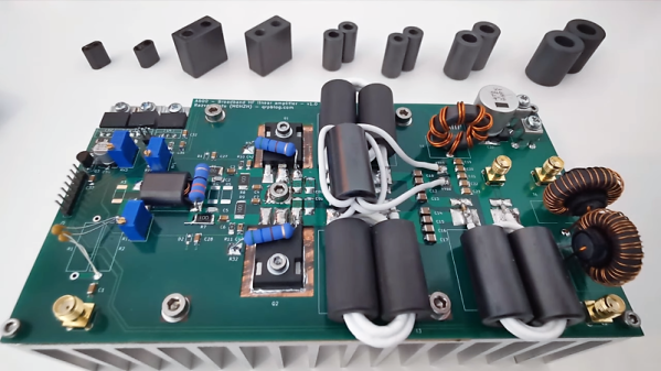
How are your RF design skills? If they’re good enough to design an RF power amp, you might want to check out this homebrew RF design challenge. Put on by NXP Semiconductors, the design must use one of their new LDMOS RF power transistors. They’ll send you samples so you can build your design, and you stand to win up to $3000 plus $1000 worth of NXP products. The contest opened back in May but is running through the middle of November, so you’d better hurry.

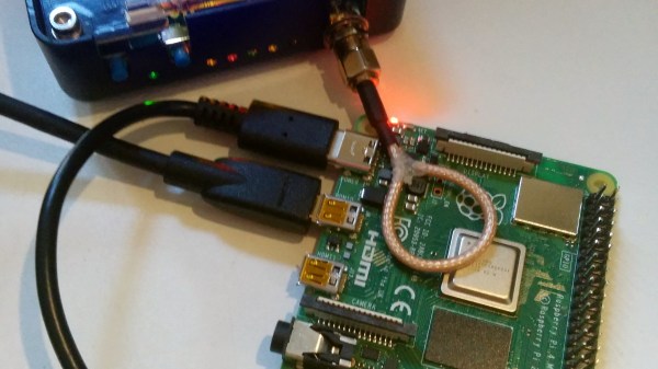
Speaking of RF, wouldn’t it be interesting to see a snapshot of the RF spectrum over the entire planet? ElectroSense thinks so, and they’re working on a crowdsourcing model to set up a globe-spanning network of connected RF sensors. The idea is similar to what FlightAware does for monitoring the locations of aircraft with a distributed network of ADS-B receivers. But where FlightAware only monitors a narrow slice of spectrum, ElectroSense wants it all – DC to 6 GHz. You can build a sensor from an SDR and a Raspberry Pi and start contributing to the effort, which only has a handful of sensors at the moment.

Has affordable metal 3D-printing finally arrived? For certain values of affordability, it soon will, when One Click Metal launches their new selective laser melting printer. Thomas Sanladerer did a video with the principals, and the prototype looks promising. SLM is not a new process, but patents on the core process recently ran out, so startups like One Click Metal are jumping into the market. Their printer won’t be cheap — you’ll still need to write a check with many zeroes — but with more players, the price should come down.

And finally, what’s this world coming to when a startup specializing in building giant fighting robots can’t make a go of it? MegaBots is shutting down, and while that’s certainly bad news for its founders and employees, it’s great news for anyone in the market for used battle bots. The company’s flagship bot, the 15-ton Eagle Prime, is currently up for auction on eBay. Bidding started at $1 with no reserve, but if you were looking for a steal, you’re a bit late. The high bid is currently $100,100, which is still an incredible buy considering it cost $2.5 million to build. You’ll have to pay for shipping, but you’ll have a super-destructive mecha of your own to drive around. And think how cool you’ll look rolling into some kid’s backyard birthday party. Presumably one you’ve been invited to.

Side-Channel Attack Shows Vulnerabilities Of Cryptocurrency Wallets

What’s in your crypto wallet? The simple answer should be fat stacks of Bitcoin or Ethereum and little more. But if you use a hardware cryptocurrency wallet, you may be carrying around a bit fat vulnerability, too.

At the 35C3 conference last year, [Thomas Roth], [Josh Datko], and [Dmitry Nedospasov] presented a side-channel attack on a hardware crypto wallet. The wallet in question is a Ledger Blue, a smartphone-sized device which seems to be discontinued by the manufacturer but is still available in the secondary market. The wallet sports a touch-screen interface for managing your crypto empire, and therein lies the weakness that these researchers exploited.

By using a HackRF SDR and a simple whip antenna, they found that the wallet radiated a distinctive and relatively strong signal at 169 MHz every time a virtual key was pressed to enter a PIN. Each burst started with a distinctive 11-bit data pattern; with the help of a logic analyzer, they determined that each packet contained the location of the key icon on the screen.

Next step: put together a training set. They rigged up a simple automatic button-masher using a servo and some 3D-printed parts, and captured signals from the SDR for 100 presses of each key. The raw data was massaged a bit to prepare it for TensorFlow, and the trained network proved accurate enough to give any hardware wallet user pause – especially since they captured the data from two meters away with relatively simple and concealable gear.

Every lock contains the information needed to defeat it, requiring only a motivated attacker with the right tools and knowledge. We’ve covered other side-channel attacks before; sadly, they’ll probably only get easier as technologies like SDR and machine learning rapidly advance.

[via RTL-SDR.com]

Complex Impedances Without The Pain

Any grizzled electronic engineer will tell you that RF work is hard. Maintaining impedance matching may be a case of cutting wires to length at lower frequencies, but into the low centimetre and millimetre wavelengths it becomes a Dark Art aided by mysterious and hugely expensive test equipment beyond the reach of mere mortals. A vector network analyser or VNA may be beyond the reach of many, but [Tomasz Wątorowski] is here to tell us about how with some resistors, mathematics, and a bit of lateral thinking its functions may be replicated with a more modestly equipped bench.

It’s not a method for the faint-hearted as the mathematics are of the variety that you probably learned as an undergraduate but let slip from your memory with thanks after the course ended. The method involves measuring the return loss both with and without a resistor of known value in series with the antenna, these figures allow the real and imaginary components of the antenna’s impedance to be calculated. There is a further piece of work though, this method doesn’t determine whether the antenna is capacitive or inductive. Repeating the measurement with either a capacitive or inductive matching network allows this to be determined, and the value of the appropriate matching component to be calculated.

If you are interested in this kind of work, start with a primer on RF design.

Complex impedance matching using scalar measurements, math and resistors

Antenna Tuning For GHz Frequencies

Antenna tuning at HF frequencies is something that radio amateurs learn as part of their licence exam, and then hone over their time operating. A few basic instruments and an LC network antenna tuner in a box are all that is required, and everything from a bit of wet string to ten thousand dollars worth of commercial antenna can be loaded up and used to work the world. When a move is made into the gigahertz range though it becomes a little more difficult. The same principles apply, but the variables of antenna design are much harder to get right and a par of wire snippers and an antenna tuner is no longer enough. With a plethora of GHz-range electronic devices surrounding us there has been more than one engineer sucked into a well of doom by imagining that their antenna design would be an easy task.

An article from Baseapp then makes for very interesting reading. Titled “Antenna tuning for beginners“, it approaches the subject from the perspective of miniature GHz antennas for IoT devices and the like. We’re taken through the basics and have a look at different types of antennas and connectors, before being introduced to a Vector Network Analyser, or VNA. Here is where some of the Black Art of high frequency RF design is laid bare, with everything explained through a series of use cases.

Though many of you will at some time or other work with these frequencies it’s very likely that few of you will do this kind of design exercise. It’s hard work, and there are so many ready-made RF modules upon which an engineer has already done the difficult part for you. But it does no harm to know something about it, so it’s very much worth taking a look at this piece.

It’s an area we’ve ventured into before, at a Superconference a few years ago [Michael Ossmann] gave us a fundamental introduction to RF design.

Fail Of The Week: The Arduino Walkie That Won’t Talkie

There’s something seriously wrong with the Arduino walkie-talkie that [GreatScott!] built.

The idea is simple: build a wireless intercom so a group of motor scooter riders can talk in real-time. Yes, such products exist commercially, but that’s no fun at all. With a little ingenuity and a well-stocked parts bin, such a device should be easy to build on the cheap, right?

Apparently not. [GreatScott!] went with an Arduino-based design, partly due to familiarity with the microcontroller but also because it made the RF part of the project seemingly easier due to cheap and easily available nRF24 2.4 GHz audio streaming modules. Everything seems straightforward enough on the breadboard – an op-amp to boost the signal from the condenser mic, a somewhat low but presumably usable 16 kHz sampling rate for the ADC. The radio modules linked up, but the audio quality was heavily distorted.

[GreatScott!] assumed that the rat’s nest of jumpers on the breadboard was to blame, so he jumped right to a PCB build. It’s a logical step, but it seems like it might be where he went wrong, because the PCB version was even worse. We’d perhaps have isolated the issue with the breadboard circuit first; did the distortion come from the audio stage? Or perhaps did the digitization inject some distortion? Or could the distortion be coming from the RF stage? We’d want to answer a few questions like that before jumping to a final design.

We love that [GreatScott!] has no issue with posting his failures – we’ve covered his suboptimal CPU handwarmer, and his 3D-printed BLDC motor stator was a flop too. It’s always nice to post mortem these things to avoid a similar fate.

Continue reading “Fail Of The Week: The Arduino Walkie That Won’t Talkie”

A DIY Step Attenuator, By Gluing Together Two Smaller Ones

In the RF world, attenuators are a useful test and measurement tool. Variable units that can apply different levels of attenuation in discrete steps are even better. [DuWayne] made a 63 dB step attenuator by putting two smaller units in series, with an Arduino Nano in control of them. With a 3D printed enclosure and OLED for feedback, the device is easily adjusted with a single rotary encoder. There was even room to add a micro USB plug for recharging the power supply.

The two smaller digital attenuators [DuWayne] used are essentially breakout boards for the PE4302 digital RF attenuator, and cheaply available from the usual overseas sources. They are capable of up to 31.5 dB of attenuation in 0.5 dB steps, and by using two in series (and controlling them in parallel) [DuWayne] gets a range of up to 63 dB. The design files can be downloaded from a Dropbox share for the project, should you wish to try any of it for yourself.

Are you interested in RF and maybe software defined radio (SDR)? We’ve covered all the stuff you’ll need to get started with an inexpensive RTL-SDR, and sooner or later you may find yourself in need of [Dan Maloney]’s info on cheap and effective dummy loads.

Camera Sees Electromagnetic Interference Using An SDR And Machine Vision

It’s one thing to know that your device is leaking electromagnetic interference (EMI), but if you really want to solve the problem, it might be helpful to know where the emissions are coming from. This heat-mapping EMI probe will answer that question, with style. It uses a webcam to record an EMI probe and the overlay a heat map of the interference on the image itself.

Regular readers will note that the hardware end of [Charles Grassin]’s EMI mapper bears a strong resemblance to the EMC probe made from semi-rigid coax we featured recently. Built as a cheap DIY substitute for an expensive off-the-shelf probe set for electromagnetic testing, the probe was super simple: just a semi-rigid coax jumper with one SMA plug lopped off and the raw end looped back and soldered. Connected to an SDR dongle, the probe proved useful for tracking down noisy circuits.

[Charles]’ project takes that a step further by adding a camera that looks down upon the device under test. OpenCV is used to track the probe, which is moved over the DUT manually with the help of an augmented reality display that helps track coverage, with a Python script recording its position and the RF power measurements. The video below shows the capture process and what the data looks like when reassembled as an overlay on top of the device.

Even if EMC testing isn’t your thing, this one seems like a lot of fun for the curious. [Charles] has kindly made the sources available on GitHub, so this is a great project to just knock out quickly and start mapping.

Continue reading “Camera Sees Electromagnetic Interference Using An SDR And Machine Vision”