 If you’re trying to detect the orientation of an object, sometimes you really don’t need a 6DOF gyro and accelerometer. Hell, if you only need to detect if an object is tilted, you can get a simple “ball in a tube” tilt sensor for pennies. [tamberg] liked this idea, but he required a tilt sensor that works in the X, Y, and Z axes. Expanding on the ‘ball in a tube’ construction of simple tilt sensors, he designed a laser cut 3D tilt sensor that does all the work of of a $30 IMU.
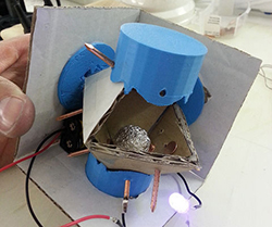
The basic design of this tilt sensor is pretty simple – just an octahedron with four nails serving as switch contacts at each vertex. An aluminum ball knocks around inside this contraption, closing the nail head switches depending on what orientation it’s in. Simple, and the three dimensional version of a ball in tube tilt sensor.
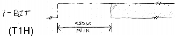
To get the tilt data to the outside world, [tamberg] is using an Adafruit Bluetooth module, with two of the nails in each corner connected to a pin. With just a little bit of code, this 3D tilt sensor becomes a six-way switch to control an RGB LED. Video of that below.