All-Band Receiver Lets You Listen To All The Radio At Once

There are many ways to build a radio receiver, but most have a few things in common, such as oscillators, tuned circuits, detectors, mixers, and amplifiers. Put those together in the right order and you’ve got a receiver ready to tune in whatever you want to listen to. But if you don’t really care about tuning and want to hear everything all at once, that greatly simplifies the job and leaves you with something like this homebrew all-band receiver.

Granted, dispensing with everything but a detector and an audio amplifier will seriously limit any receiver’s capabilities. But that wasn’t really a design concern for [Ido Roseman], who was in search of a simple and unobtrusive way to monitor air traffic control conversations while flying. True, there are commercially available radios that tune the aviation bands, and there are plenty of software-defined radio (SDR) options, but air travel authorities and fellow travelers alike may take a dim view of an antenna sticking out of a pocket.

So [Ido] did a little digging and found a dead-simple circuit that can receive signals from the medium-wave bands up into the VHF range without regard for modulation. The basic circuit is a Schottky diode detector between an antenna and a high-gain audio amplifier driving high-impedance headphones; [Ido] built a variation that also has an LM386 amplifier stage to allow the use of regular earbuds, which along with a simple 3D-printed case aids in the receiver’s stealth.

With only a short piece of wire as an antenna, reception is limited to nearby powerful transmitters, but that makes it suitable for getting at least the pilot side of ATC conversations. It works surprisingly well — [Ido] included a few clips that are perfectly understandable, even if the receiver also captured things like cell phones chirping and what sounds like random sferics. It seems like a fun circuit to play with, although with our luck we’d probably not try to take it on a plane.

Linear Power Supply’s Current Limiter Is A Lesson In Simplicity

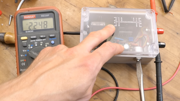
Here at Hackaday we really like to feature projects that push the limits of what’s possible, or ones that feature some new and exciting technology that nobody has ever seen before. So what’s so exciting about this single-voltage linear power supply? Honestly, nothing — until you start looking at its thermally compensated current limiting circuit.

This one is by [DiodeGoneWild], who you’ve really got to hand it to in terms of both the empirical effort he went through to optimize the circuit, as well as the quality of his explanation. The basic circuit is dead simple: a transformer, a full-wave rectifier, an LD1085 adjustable regulator — a low-dropout version of the venerable LM317 — and associated filter caps and trimmer pot to adjust the output between 2.2 and 5.5 volts.

The current limiting circuit, though, is where things get interesting. Rather than use an op-amp, [DiodeGoneWild] chose a simple discrete transistor current-sense circuit. To make it less susceptible to thermal drift, he experimented with multiple configurations of resistors and Schottky diodes over a wide range of temperatures, from deep-freeze cold to hair-dryer-in-a-box hot. His data table and the resulting graph of current versus temperature are works of art, and they allowed him to make sensible component selections for a fixed 250-mA current limit with a reasonably flat thermal response.

As for construction, it’s all classic [DiodeGoneWild], including a PCB with traces ground out with a Dremel and a recycled heat sink. He also dropped a couple of interesting build techniques, like adding leads to turn SMD tantalum caps into through-hole components. The video below shows all the build details along with the exhaustive breadboard testing.

From taking on a potentially risky magnetron teardown to harvesting lasers from headlights, there’s always something to learn from a [DiodeGoneWild] video.

Continue reading “Linear Power Supply’s Current Limiter Is A Lesson In Simplicity”

Low-Cost RF Power Sensor Gets All The Details Right

Dirty little secret time: although amateur radio operators talk a good game about relishing the technical challenge of building their own radio equipment, what’s really behind all the DIY gear is the fact that the really good stuff is just too expensive to buy.

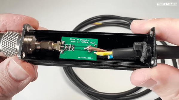
A case in point is this super-low-cost RF power sensor that [Tech Minds (M0DQW)] recently built. It’s based on a design by [DL5NEG] that uses a single Schottky diode and a handful of passive components. The design is simple, but as with all things RF, details count. Chief among these details is the physical layout of the PCB, which features a stripline of precise dimensions to keep the input impedance at the expected 50 ohms. Also important are the number and locations of the vias that stitch the ground planes together on the double-sided PCB.

While [Tech Minds]’ first pass at the sensor hewed closely to the original design and used a homebrew PCB, the sensor seemed like a great candidate for translating to a commercial PCB. This version proved to be just as effective as the original, with the voltage output lining up nicely with the original calibration curves generated by [DL5NEG]. The addition of a nice extruded aluminum case and an N-type RF input made for a very professional-looking tool, not to mention a useful one.

[Tech Minds] is lucky enough to live within view of QO-100, ham radio’s first geosynchronous satellite, so this sensor will be teamed up with an ADC and a Raspberry Pi to create a wattmeter with a graphical display for his 2.4-GHz satellite operations.

Continue reading “Low-Cost RF Power Sensor Gets All The Details Right”

Solar Panel Keeps Car Battery Topped Off Through OBD-II Port

Up until the 1980s or so, a mechanic could check for shorts in a car’s electrical system by looking for sparks while removing the battery terminal with everything turned off in the car. That stopped being possible when cars started getting always-on devices, and as [Kerry Wong] learned, these phantom loads can leave one stranded with a dead battery at the airport after returning from a long trip.

[Kerry]’s solution is simple: a solar trickle charger. Such devices are readily available commercially, of course, and generally consist of a small photovoltaic array that sits on the dashboard and a plug for the lighter socket. But as [Kerry] points out in the video below, most newer model cars no longer have lighter sockets that are wired to work without the ignition being on. So he chose to connect his solar panel directly to the OBD-II port, the spec for which calls for an always-on, fused circuit connected directly to the positive terminal of the vehicle battery. He had to hack together an adapter for the panel’s lighter plug, the insides of which are more than a little scary, and for good measure, he added a Schottky diode to prevent battery discharge through the panel. Even the weak winter sun provides 150 mA or so of trickle charge, and [Kerry] can rest assured his ride will be ready at the end of his trip.

We used to seeing [Kerry] tear down test gear and analyze unusual devices, along with the odd post mortem on nearly catastrophic failures. We’re glad nothing burst into flames with this one.

Continue reading “Solar Panel Keeps Car Battery Topped Off Through OBD-II Port”

Handy Continuity Tester Packs Multiple Modes Into A Tiny Package

From Leatherman multitools to oscilloscopes with built-in signal generators and protocol analyzers, there seems no end to tools with multiple personalities. Everybody loves multitaskers because they make it feel like you’re getting more bang for your buck, and in most cases that’s true. But a jack of all trades is seldom master of any, and there are times when even the humble multimeter isn’t the best tool for the job.

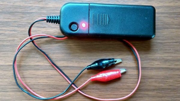
With that in mind, [sidsingh] has developed what we think is a very nice dedicated continuity tester. With a goal of using only parts on hand, he had to think small to fit everything into the case he had. So he started with a PIC10LF322 to support all the flavors of continuity testing he wanted to support. In addition to straight continuity, the tester can handle diode testing, detecting shorted or open diodes and even differentiating between regular and Schottky diodes. It also has an LED test mode and an interesting “discontinuity” testing mode — it only sounds its buzzer when continuity is broken. The video below shows that mode in action for finding intermittent cable faults, along with all the other modes.

For an ostensibly single-purpose tool, this tester still manages to pack a lot of tests into one very compact package. Simpler continuity testers are good, too — check out this cheap dollar store build, or this slightly more complicated unit based on an ATtiny85.

Continue reading “Handy Continuity Tester Packs Multiple Modes Into A Tiny Package”

Diodes With Hats: Zener And Schottky

For beginners, diode types can sometimes be a bit of mental gymnastics. If all it does is act like a magic pixie check valve, why are there so many kinds? Schottky diodes are typically  hard to mentally set apart from the standard when described by a data sheet. Zener diodes can be downright baffling for beginners, especially when mistakenly thrown in a circuit in place of a regular 1N4001. [Afrotechmods] put together a great video explaining their difference and use cases.

In both videos he does an excellent job of describing the pros and cons while setting up experiments to exhibit each. For the Schottky it’s the faster switching and lower voltage drop. For Zener it’s less about the cons and more about exploiting its strange configuration for voltage clamps, regulators, and making expensive guitars sound bad with audio distortion circuits.

He finishes both videos with good design tips for selecting and using the parts as a burgeoning circuit designer. Diode data sheets should be less of a mystery afterwards.

Continue reading “Diodes With Hats: Zener And Schottky”

History Of The Diode

The history of the diode is a fun one as it’s rife with accidental discoveries, sometimes having to wait decades for a use for what was found. Two examples of that are our first two topics: thermionic emission and semiconductor diodes. So let’s dive in.

Vacuum Tubes/Thermionic Diodes

Our first accidental discovery was of thermionic emission, which many years later lead to the vacuum tube. Thermionic emission is basically heating a metal, or a coated metal, causing the emission of electrons from its surface.

Electroscope
Electroscope

In 1873 Frederick Guthrie had charged his electroscope positively and then brought a piece of white-hot metal near the electroscope’s terminal. The white-hot metal emitted electrons to the terminal, which of course neutralized the electroscope’s positive charge, causing the leafs to come together. A negatively charged electroscope can’t be discharged this way though, since the hot metal emits electrons only, i.e. negative charge. Thus the direction of electron flow was one-way and the earliest diode was born.

Thomas Edison independently discovered this effect in 1880 when trying to work out why the carbon-filaments in his light bulbs were often burning out at their positive-connected ends. In exploring the problem, he created a special evacuated bulb wherein he had a piece of metal connected to the positive end of the circuit and held near the filament. He found that an invisible current flowed from the filament to the metal. For this reason, thermionic emission is sometimes referred to as the Edison effect.

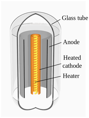
Thermionic diode
Thermionic diode. By Svjo [CC BY-SA 3.0], via Wikimedia Commons
But it took until 1904 for the first practical use of the effect to appear. John Ambrose Fleming had actually consulted for the Edison Electric Light Company from 1881-1891 but was now working for the Marconi Wireless Telegraph Company. In 1901 the company demonstrated the first radio transmission across the Atlantic, the letter “S” in the form or three dots in Morse code. But there was so much difficulty in telling the received signal apart from the background noise, that the result was disputed (and still is). This made Fleming realize that a more sensitive detector than the coherer they’d been using was needed. And so in 1904 he tried an Edison effect bulb. It worked well, rectifying the high frequency oscillations and passing the signals on to a galvanometer. He filed for a patent and the Fleming valve, the two element vacuum tube or thermionic diode, came into being, heralding decades of technological developments in many subsequent types of vacuum tubes.

Vacuum tubes began to be replaced in power supplies in the 1940s by selenium diodes and in the 1960s by semiconductor diodes but are still used today in high power applications. There’s also been a resurgence in their use by audiophiles and recording studios. But that’s only the start of our history.

Continue reading “History Of The Diode”