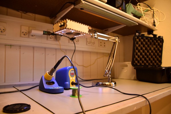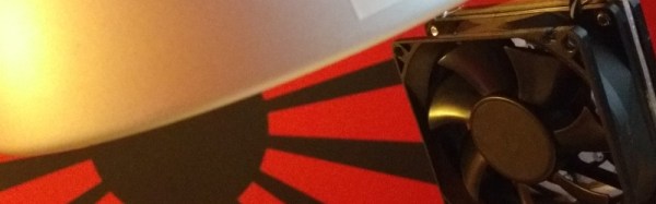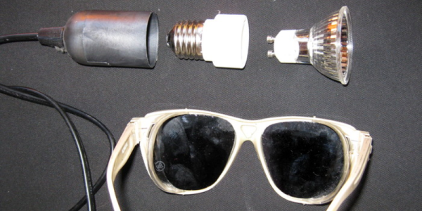
[Moony] thought that it was unconscionable that IR soldering stations sell for a few hundred Euros. After all, they’re nothing more than a glorified halogen lightbulb with a fancy IR-pass filter on them. Professional versions use 100 W 12 V DC bulbs, though, and that’s a lot of current. [Moony] tried with a plain-old 100 W halogen lightbulb. Perhaps unsurprisingly, it worked just fine. Holding the reflector-backed halogen spotlight bulb close to circuit boards allows one to pull BGAs and other ornery chips off after a few minutes. Voila.
[Moony] reasons that the IR filter is a waste anyway, since the luminous efficiency of halogen lights is so low: around 3.5%. And that means 96.5% heat! But there’s still a lot of light streaming out into a very small area, so if you’re going to look at the board as you de-solder, you’re really going to need a pair of welding goggles. Without, you’ll have a very hard time seeing your work at best, and might actually do long-term damage to your retinas.
So the next time you’re feeling jealous of those rework factory workers with their fancy IR soldering stations, head on down to the hardware store, pick up a gooseneck lamp, a 100 W halogen spotlight, and some welding goggles. And maybe a fire brick. You really don’t want your desk going up in flames.
We love make-do hacks, but we love doing it right, too. Just watch [Bil Herd] extol the virtues of a real IR desoldering station. And then giggle as you do the same thing with a few-dollar halogen bulb.
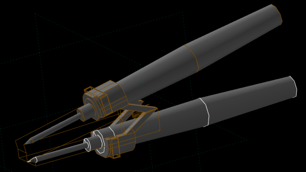
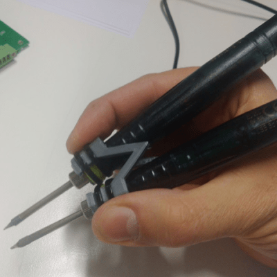 [adria.junyent-ferre] took a pair of cheap £5 USB soldering irons and turned them into a nifty pair of