Who Needs The MSP430 When You Have TI’s Other Microcontroller, The TI-84?

We’re sure there are more expensive LED controllers out there, but the TI-84 has got to be up there. Unless you have one on hand, then it’s free. And then you’ll doubtless need an SPI library for the famously moddable graphing calculator.

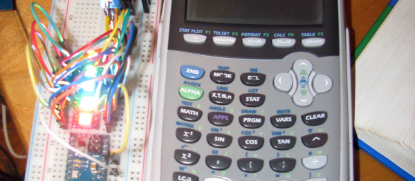
[Ivoah] is using his library, written in assembly for the Z80 processor inside the TI, to control a small strip of DotStar LEDs from Adafruit. The top board in the photograph is an ESP8266 board that just happened to be on the breadboard. The lower Arduino is being used as a 5V power supply, relegated to such duties in the face of such a superior computing device.

Many of us entertained ourselves through boring classes by exploring the features of TI BASIC, but this is certainly a step above. You can see his code here on his GitHub.

After his proof-of-concept, [Ivoah] also made a video of it working and began to program a graphical interface for controlling the LEDs. Video after the break.

Continue reading “Who Needs The MSP430 When You Have TI’s Other Microcontroller, The TI-84?”

Pi Zero Video Card Via Bare Metal Programming

Rolling your own synthesizer is no small feat, which is what [Thomas] has taken on with his project “Nerdsynth”. [Thomas] has an impressive amount of data on his site covering the overall design and progress of the project, but that isn’t what piqued our interest. [Thomas] has an on-board TFT display to navigate the versatile Nerdsynth’s menu nerdsynth-sketchbut he wanted to add video output to  do some video sequencing. After some investigation and poking around the available options he decided to tackle yet another sub-project (textbook scope-creep).

[Thomas] chose to do to some bare metal programming on the Pi Zero to use it as a video card for video output. By following a tutorial  from Valvers and modifying an SPI driver from Microelecroniki he was able to clone the video on an external monitor. This is a step in the right direction and we’ll have to keep an eye on his site for updates about video sequencing on the external display.

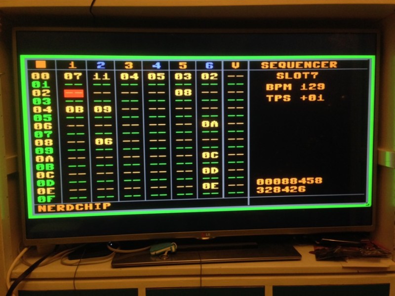
You can check out a recent demo of the Nerdsynth in action after the break, sadly you’ll have to settle for a pic of the cloned screen (below) until [Thomas] posts another update.

nerdsynth_tv-942x707

Continue reading “Pi Zero Video Card Via Bare Metal Programming”

SPI: Let Go And Use The Force

Take a leap the next time you use SPI and don’t poll for the busy flag. “What, are you crazy? That’s the whole point of the busy flag! It’s a quick check to make sure you don’t kill a byte waiting to be shifted out!” Sure, we thought the same thing, but the other side of the coin is that it takes time to check the busy flag, and that’s time he could be transmitting data. [bigjosh2] calculates that his technique saves 20% of those wasted cycles in this particular case. And he’s “using the force” only because he’s a Jedi master able to rely on the cycle count of a chunk of assembly code.

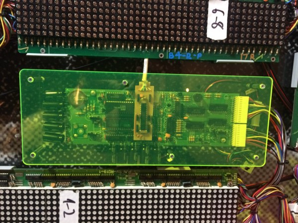
He’s working with an AVR processor, and pumping out bits to drive the vintage LED display pictured above. The ancient chips don’t have buffered SPI so he has to blank the display while shifting new data in to prevent it from glitching. Because the display blank during the SPI transmission, the slower it goes, the dimmer the lights.

He attacks the problem with synchronous code. It takes 2 cycles for the hardware SPI to send each bit, so he twiddles his thumbs (that’s exactly what he wrote in his code comments) for 16 cycles before reloading the SPI register with his next value. This leaves it up to faith in the silicon that the shifting will always take the same number of cycles, but the nice thing about hardware is that it’s deterministic. He ends up killing a few cycles in order to save time by not polling the busy flag.

Still need a crash course in what SPI actually does? [Bil Herd] has you covered with this SPI communication demo.

Pi Zero Ethernet The Hard Way

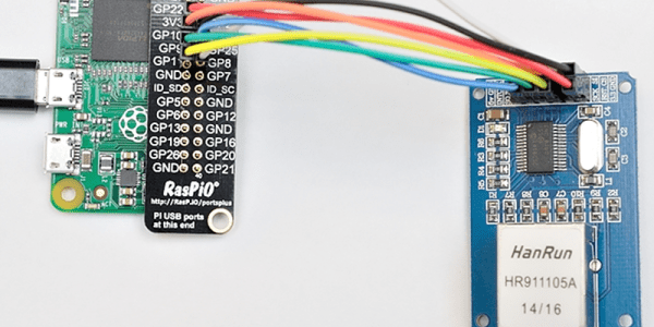
[Alex@Raspi.tv] had the misfortune of blowing the USB hub and Ethernet port on a Raspberry Pi B+. He thought about using a cheap SPI to Ethernet board to rescue it, and while he bought the board, he never got around to interfacing it to the broken Pi. However, when he saw the Raspberry Pi Zero arrive and noticed that everyone wanted to connect it to the network, he remembered the SPI board, rescued it from his junk box, and a few hours later had Ethernet via Raspberry Pi GPIO working.

Continue reading “Pi Zero Ethernet The Hard Way”

Hacking 2.4GHz Radio Control

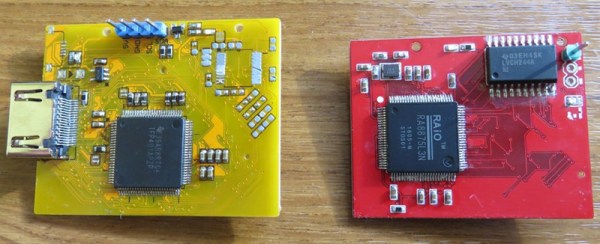
Many modern radio control (RC) systems use frequency hopping to prevent interference. Unfortunately, hopping all over the 2.4GHz band can interfere with video or WiFi using the same frequency band. [Befinitiv] was trying to solve this problem when he realized that most of the systems used a TI CC2500 chip and a microcontroller. The microcontroller commands the chip via SPI and controls the frequency by writing into a frequency register.

Updating the microcontroller firmware was impractical. The firmware is encrypted, for one thing. In addition, the change would have to be reinserted on any future updates and repeated for every RC vendor. So [Befinitiv] took a different approach. He did a classic man in the middle attack by inserting an CPLD in between the controller and the CC2500.

Continue reading “Hacking 2.4GHz Radio Control”

LED Matrix Failure And Vindication

If necessity is the mother of invention, what’s failure the mother of? Improvement? Anyway, [prpplague]’s second version of his roll-up 70×30 RGB LED display looks a lot better and more reliable than the first, and that’s precisely due to “failing”.

Sometimes you design the hardware around the software, and sometimes vice-versa. It’s all about the balance of pain. [prpplague] initially wired the strips together in a consistently left-to-right raster arrangement to make the coding easier, but this means long wires on the backside of the fabric returning from the right side back to the start again at the left. These long wires snagged on stuff, and pulled the solder connections apart.

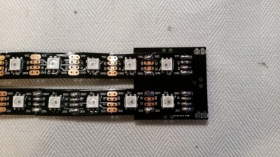
600px-Dotstar-adapter-solder3The fix? Alternate rows of left-to-right with right-to-left to minimize wiring and make nice, robust connectors for the ends, and a much more elegant implementation at the expense of more complicated software to drive the device. (Alternating rows have to be flipped horizontally, so this means custom driver routines.)

The second gremlin was that the interfacing board that [prpplague] was using didn’t have enough current sourcing capability on the SPI lines, and he discovered that he couldn’t communicate reliably with the strings if the first pixel was more than 24″ of wire away from the board. Once the signal got to the first pixel, though, everything was fine. [prpplague] figured out that the RGB LEDs themselves had more drive capability than the SPI source.

The solution? Add a single pixel at the front of the chain to buffer the SPI lines and serve as a bonus status indicator. Cute.

We’d hardly call these “fails”, but rather “learning experiences”. Anyway, here’s two design “mistakes” that we won’t make when making a roll-up flexible pixel display. Thanks [prpplague].

Embed With Elliot: Multiplexing SPI Uses Few Pins

[Ralph Doncaster], aka Nerdralph, seems to be absolutely driven to see how few resources he can use on a microcontroller to get the job done. In this post on his blog, [Ralph] writes some custom bit-banged SPI code to cut the number of SPI lines necessary to drive an nRF24L01+ radio module from four down to two. That really helps if you’re using a micro with only six free pins, like an ATtiny85.

If you’re going to say, “why don’t you just buy a bigger microcontroller?”, you’re missing the point. This exercise strikes us as optimization for optimization’s sake and a dirty hack, both of which are points in its favor.  There are also a couple of techniques here for your mental toolbox. We thought it was interesting enough to look at in depth.

Continue reading “Embed With Elliot: Multiplexing SPI Uses Few Pins”