Mains Power Supply For ATtiny Project Is Probably A Bad Idea

When designing a mains power supply for a small load DC circuit, there are plenty of considerations. Small size, efficiency, and cost of materials all spring to mind. Potential lethality seems like it would be a bad thing to design in, but that didn’t stop [Great Scott!] from exploring capacitive drop power supplies. You know, for science.

The backstory here is that [Great Scott!] is working on a super-secret ATtiny project that needs to be powered off mains. Switching power supplies are practically de rigueur for such applications, but compared to the intended microcontroller circuit they are actually quite large, and they’ve just been so done before. So in order to learn a thing or two, [Scott!] designed a capacitive dropper supply, where the reactance of the cap acts like a dropping resistor to limit the current. His first try was just a capacitor in series with an LED; this didn’t end well for the LED.

To understand why, he reverse-engineered a few low-current mains devices and found that practical capacitive droppers need a few more components, chiefly a series resistance to prevent inrush current from getting out of hand, but also a bridge rectifier and a zener to clamp things down. Wiring up all that resulted in a working capacitive dropper supply, but a the cost of as much real estate as a small switcher, and with the extra bonus of being potentially lethal if the power supply is plugged in the wrong way. Side note: we thought German line cords were polarized to prevent this, but apparently not? (Ed Note: Nope!)

As always, even when [Great Scott!]’s projects don’t exactly work out, like a suboptimal 3D-printed BLDC or why not to bother building your own DC-AC inverter, we enjoy the learning that results.

Continue reading “Mains Power Supply For ATtiny Project Is Probably A Bad Idea”

Bench Power Supply Uses Server Voltage Regulator

If you stuff a computer into a rack with a bunch of other machines, you’d better make it a tough machine. Server-grade means something, so using server parts in a project, like this high-wattage power supply using server voltage regulators, can take it to the next level of robustness.

But before [Andy Brown] could build this power supply, he had to reverse-engineer the modules. Based on what he learned, and armed with a data sheet for the modules, he designed a controller to take advantage of all the capabilities of them and ended up with a full-featured power supply. The modules are rated for 66 watts total dissipation at 3.3 volts and have a secondary 5-volt output. Using an ATmega328, [Andy] was able to control the module, provide a display for voltage and current, temperature sensing and fan control, and even a UART to allow data logging to a serial port. His design features mainly through-hole components to make the build accessible to everyone. A suitable case is yet to come, and we’re looking forward to seeing the finished product.

Can’t scrape together some of these modules on eBay? Or perhaps you prefer linear power supplies to switched- mode? No worries – here’s a super stable unregulated supply for you.

Continue reading “Bench Power Supply Uses Server Voltage Regulator”

A Primer On Buck (and Boost) Converters

We all know that the reason the electrical system uses alternating current is because it’s easy to step the voltage up and down using a transformer, a feature which just isn’t possible with a DC system… or is it? Perhaps you’ve heard of mysterious DC-DC transformers before but never really wanted to look at the wizardry that makes them possible. Now, SparkFun Director of Engineering [Pete Dokter] has a tutorial which explains how these mysterious devices work.

Known as buck converters if they step the input voltage down and boost converters if they step the voltage up, [Pete] explains how these circuits exploit the properties of an inductor to resist changes in current flow. He goes into exquisite detail to explain how components like transistors or MOSFETs are used to switch the current flow to the inductor very rapidly, and just exactly what happens to the magnetic field which makes these devices possible.

The video gives a good amount of background knowledge if you’ve always wanted to understand these devices a little bit better. There are also a few projects floating around that exploit these devices, such as one that uses an AVR microcontroller to perform the switching for a small circuit, or another that uses the interesting properties of these circuits to follow the I-V curve of a solar panel to help charge a bank of batteries. The possibilities are endless!

Continue reading “A Primer On Buck (and Boost) Converters”

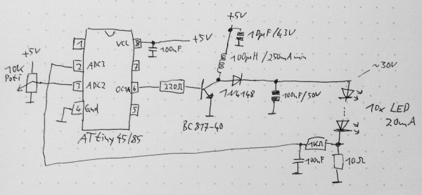
Schematic for a boost converter based on the ATtiny MCU

An ATtiny Boost Converter

This schematic is all you need to build your own voltage converter. [Lutz] needed a converter that could boost 5 V to 30 V to power a string of LEDs. The solution was to use low cost ATtiny85 and some passive components to implement a boost converter.

This circuit follows the classic boost converter topology, using the ATtiny85 to control the switch. The 10 ohm resistor is fed back into the microcontroller’s ADC input, allowing it to sense the output voltage. By measuring the output voltage and adjusting the duty cycle accordingly, the circuit can regulate to a specified voltage setpoint.

A potentiometer is used to change the brightness of the LEDs. The software reads the potentiometer’s output voltage and adjusts the voltage output of the circuit accordingly. Higher voltages result in brighter LEDs.

Of course, there’s many other ways to implement a boost converter. Most practical designs will use a chip designed for this specific purpose. However, if you’re interested in rolling your own, the source and LTSpice simulation files are available.

logo if acdc band

Ask Hackaday: Who Wants An All DC House?

Sometimes when working on a righteous hack, we get goosebumps while watching our code execute faster than we could ever possibly comprehend. Seeing the pixels of the LCD come alive, hearing the chatter of relays and the hum of fans…it’s an amazing thing what electricity can do. And it is equally amazing when you realize that it all started one hundred and thirty five years ago, when [Thomas Edison] changed the world forever with the first practical electric light bulb.

That bulb was lit by a Direct Current – the same thing that runs the computer you’re reading this article on. The same thing that runs many of the hacks you read about here on Hack a Day, and almost all electronic devices in your house. But somewhere in the mix must exist a device that changes the Alternating Current from your wall outlet to the needed DC. Why? Why is it that we transport electricity as AC only to convert it to DC in our homes? You might answer:

“This argument was played out in the War of Currents back in the 1880’s.”

Indeed, it was. But that was a long time ago. Technology has changed. Changed so much to the point that the arguments in the War of Currents might no longer be valid. Join us after the break, where we rehash these arguments, and explore the feasibility of an all DC environment.

Continue reading “Ask Hackaday: Who Wants An All DC House?”

Replace Your Project Power Supplies With Recycled Li-Ion Cells And A Switching Regulator

buck-regulator

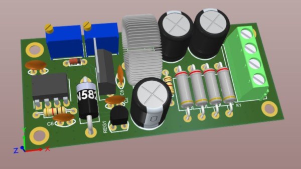
[Dr. Iguana’s] experience moving from projects powered by disposable Alkaline cells and linear regulators to recycled Lithium Ion cells using the buck regulators seen above might serve as an inspiration to make the transition in your own projects.

The recycled cells he’s talking about are pulled out of larger battery packs. As we’ve seen in the past, dead battery packs for rechargeable tools, laptops, etc., are often plagued by a few bad apples. A small number of dead cells can bork the entire battery even though many perfectly usable cells remain. Once he decided to make the switch it was time to consider power regulation. He first looked at whether to use the cells in parallel or series. Parallel are easier to charge, but boosting the voltage to the desired level ends up costing more. He decided to go with cells in series, which can be regulated with the a less expensive buck converter. In this case he made a board for the RT8289 chip. The drawback of this method requires that you monitor each cell individually during charging to ensure you don’t have the same problem that killed the battery from which you pulled these good cells.

VFD Tube Clock Built Using Protoboard And Free-formed PSU

[James Glanville] wrote in to show of his latest tube project. It’s a clock using six IV-3 VFD tubes. In addition to the tube displays the project prominently features a blue 3D printed case which hides away all the guts of the build including the Stellaris Launchpad which drives the clock.

Speaking of guts, you’ll want to look through a few of [James’] other posts on the project. His first write-up on this clock shows off the protoboard and point-to-point soldering that makes the tubes work. To help simplify things he went with a MAX6921 VFD driver chip. He mounted it dead-bug style on its own piece of protoboard and then soldered all of the necessary connections to the larger hunk hosting the tubes. There’s also an interesting post that details the switch mode power supply which ramps the USB 5V power all the way up to the 50V used to drive the displays.

If you like this you should check out the first VFD clock he built. We featured it a while back in a links post.