Redlining Your CPU Via Automotive Tachometer

Many CPU-usage widgets have stylistically borrowed from vehicles, displaying something mimicking the tachometer found in the dashboard. [Pat] took it a step further and tried his hand at re-borrowing this style. He figured, why not use an actual physical tachometer to display how hard the CPU on his Raspberry Pi was revving?

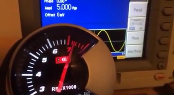
With the goal of tuning 0-100% CPU usage to 0-8000 RPM on the tach, the first step was diagnosing the range of PWM input frequencies that moved the needle across the tach’s full arc. Using his Tektronix 3252C function generator he quickly determined 0-440 Hz would be needed and graphed a handful of intermediate points. The response curve was not linear, so he drew up some fudging guidelines to make all the datapoints match.

Next, he wrote a few lines of Python (he shared) to make the Pi to poll its CPU usage and translate it to the proper frequency. The Pi makes outputting easy, GPIO pin 11 carried the signal to a 7404 for buffering, then out to the tach. The automotive tach itself ran on 12V, but its input signal required only 5V so he pulled a 7805 from his parts bin.

Once it was all put together it worked beautifully using just the one extra component. Some might see this as more clever than USB dependent or Arduino bloated based tachometer hacks.

See the video after the break of the tach twitching even when the mouse moved, and pegging the red when opening a browser. No more need to use up valuable screen real-estate (or use a screen at all) if you want to see at a glance when your Pi is putting in work.

Continue reading “Redlining Your CPU Via Automotive Tachometer”

tachtastic diy tachometer

Fantastic Tach Is Strangely Called Tachtastic

We all have projects from yesteryear that we wish had been documented better. [EjaadTech] is fighting back by creating a project page about a tachometer he built 3 years ago while in college. He’s done a great write-up documenting all the steps from bread-boarding to testing to finished project. All of the code necessary for this tachometer is available too, just in case you’d like to make one yourself.

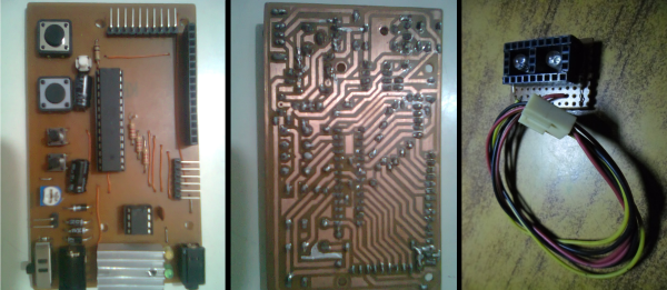
At the heart of the project is an AVR ATMega8 chip that performs the calculations and controls the LCD output screen that displays both the immediate RPM as well as the average. To hold everything together, [EjaadTech] etched his own custom PCB board that we must say looks pretty good. In addition to holding all the necessary components, there is also an ISP connector for programming and re-programming.

There are two attachment options for sensing the RPM. One is a beam-break style where the IR emitter is on one side of the object and the receiver is on the other. This type of sensor would work well with something like a fan, where the blades would break the IR beam as they passed by. Then other attachment has the IR emitter and receiver on one board mounted next to each other. The emitter continually sends out a signal and the receiver counts how often it sees a reflection. This works for rotating objects such as shafts where there would not be a regular break in the IR beam. For this reflective-based setup to work there would have to be a small piece of reflective tape on the shaft providing a once-per-revolution reflection point. Notice the use of female headers to block any stray IR beams from causing an inaccurate reading… simple and effective.

Visualize Vroom With This RGB LED Tachometer

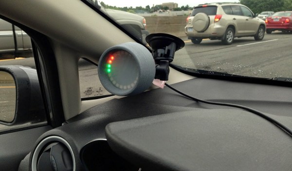
[Pete Mills] recently bought the all-new Ford Fiesta, which offers impressive fuel economy over that of his Jeep. He soon figured out that he has real time access to a wealth of engine and chassis data through Ford’s OpenXC platform and used it to build blueShift, a neopixel tachometer. The car already has a tach, but this one is more visual, can be seen in periphery, and is just plain fun.

In case you hadn’t heard, the OpenXC platform is Ford’s consumer key to the kingdom of OBD2 treasures. It unlocks the magic through its Vehicle Interface, which plugs into the OBD2 port and translates the CAN bus messages to OpenXC format. These messages are packaged into JSON format and can be sent over Bluetooth or Ethernet/Wi-Fi to an Android, Python, or iOS device.

[Pete] went with Bluetooth and used a BlueSMiRF with an Arduino Pro Mini. He derives power from the car’s on-board USB port, but has future plans to use the OpenXC VI port. blueShift reads the RPM data and displays a green trail as the engine revs up. At the peak revolution, it shows a red LED. This one is sticky and will persist for the lesser of three seconds or the time elapsed to a new positive RPM. [Pete] is also reading the headlight status of the car. As soon as they come on, the RGB LEDs dim to avoid blinding him at night.

[Pete] wanted to make an enclosure more finished-looking than a Tupperware box. He nearly detoured into 3D-printer design, but ended up putting together a Prusa i3v and came up with this RAM mount-compatible enclosure. His fantastic write-up and code are on his blog, but you can make the jump to see a short demo and a full explanation video. You can also make smart brake lights or even create art with OpenXC.

Continue reading “Visualize Vroom With This RGB LED Tachometer”

Sound Card Tachometer Rises From The Junkbox

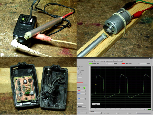
We love writing up projects that re-use lots of old parts. In fact, we save the links and use them as defense when our significant other complains about the “junk” in the basement. No, that tactic hasn’t ever worked, but we’re going to keep trying. Case in point, [Wotboa] needed a non-contact tachometer. There are plenty of commercial products which do just that. After consulting his parts bin, [wotboa] realized he had everything he needed to hack out his own. An IR break beam sensor from an old printer was a perfect fit in an aluminum tube. With the outer shell removed, the emitter and detector were mounted in the nylon shell of an old PC power supply connector, effectively turning them pair into a reflective sensor. To amplify the circuit, [wotboa] used a simple 2n2222 transistor circuit. The key is to keep the voltage seen by the sound card the range of a line level signal. This was accomplished by adding a 2.2 Megohm resistor in line with the output. [wotboa] drew his schematic in eagle, and etched his own PCB for the project. Even the tachometer’s case came from the parts bin. An old wall wart power supply gave up its shell for the cause, though [wotboa] is saving the transformer for another project.

For sensing, [wotba] used [Christian Zeitnitz’s] Soundcard Oscilloscope software.  Measuring the RPM of the device under test is simply a matter of determining the frequency of the signal and multiplying by 60. A 400 Hz signal would correspond to a shaft turning at 24,000 RPM. The circuit performs well in the range of RPM [wotboa] needs, but using a sound card does have its limits. The signals on the scope look a bit distorted from the square waves one would expect. This is due to the AC coupled nature of sound cards. As the signal approaches DC, the waveform will become more distorted. One possible fix for this would be to remove the AC coupling capacitor on the sound card’s input. With the capacitor removed, an op amp buffer would be a good idea to prevent damage to the sound card.

[Via Instructables]

Arduino Tachometer Tutorial

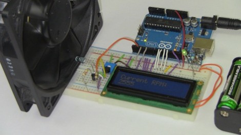
This tutorial will guide you through the process of building a tachometer around an Arduino. Tachometers are used to measure rotation rate in Revolutions Per Minute (RPM). You don’t need much in the way of hardware, this version uses an Infrared beam to measure fan speed. As with last year’s PIC-based tutorial, [Chris] is using a character LCD to output the reading. Wiring and driving the LCD ends up being the hardest part.

An IR transmitter/receiver pair are positioned on either side of the fan. When the blade passes in between then, the receiver shuts off a transistor connected to one of the Arduino’s external interrupt pins. He shows how to use this interrupt to measure the amount of time between the passing of each fan blade. If you divide for the number of blades, and average the reading for greater accuracy, you can easily calculate RPM.

Another alternative would have been to use a reflectance sensor which allows to for the transmitter and receiver to both be on the same side of the fan.

Junkyard Scavenging Nets A Tachometer To Play With

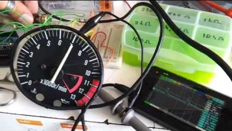
We never thought to hit the automotive junkyard to find electronics we could play with. But [Istimat] was able to pull this working tachometer from an otherwise destroyed motorcycle dashboard. The Kawasaki part has just three pins on the back of it. By connecting 12V to the IGN pin, ground to GND, and tapping a 12V wire on the unlabeled pin he was able to make the needle dance and knew he was getting somewhere.

His microcontroller of choice for the project is an Arduino board. But the 5V logic levels aren’t going to put out the square wave needed to drive the device. A search of the internet led him to a 2-transistor circuit which lets him get the results seen in the video. His plan is to add functionality that uses the Arduino to pull data in from just about any source and display it on the dial. That computer desk that featured all the CPU load readouts immediately comes to mind.

Do you think the square wave circuit is more complicated than necessary? Could this be done with just one NPN transistor and a pair of resistors?

Continue reading “Junkyard Scavenging Nets A Tachometer To Play With”

Digital Speedometer With An Arduino

[Martyn] is restoring a 32-year-old Honda motorcycle, so when the ancient speedometer broke last year he thought it was prime time to start of a digital speedometer project. We’re loving the results so far, and would love seeing it on a nicely restored bike.

Instead of the relative horror of driving 40 LEDs with a single Arduino, [Martyn] bit the bullet and got a Maxim 7221 LED driver. Controlling 64 LEDs  over a three-wire interface simplified the board design somewhat, allowing [Martyn] to etch his own PCB with the toner transfer & HCl/H2O2 method. To actually power and control the entire circuit, [Martyn] used an Arduino loaded up with a program based  LedControl library makes programming the spedometer a snap.

Although the speedo works, [Martyn] says he isn’t proud of how it looks. We don’t mind – the candy colored jumpers add a nice flair to the project, and they’re hidden behind the face plate of the speedometer. We’re sure once he gets the neutral, high-beam, and warning indicators working with the LED bar array / tachometer, everything will look awesome.

via reddit