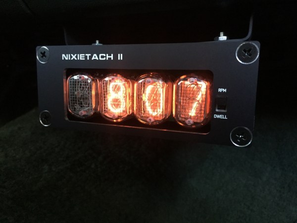
Nixietach II is a feature-rich tachomoter [Jeff LaBundy] built for his 1971 Ford LTD. It displays RPM with an error rate of only 0.03 RPM at 1,000 RPM
The latest iteration of a long-running project, [Jeff] approached it with three goals: the tachometer had to be self-contained and easy to install, the enclosure had to be of reasonable size, and it had to include new and exciting features over the first two versions.
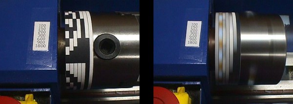
The finished project consists of an enclosure mounted under the dash with a sensor box in the engine bay connected to the ignition coil. He can also flip a switch and the Nixietach serves as a dwell sensor able to measure the cam’s angle of rotation during which the ignition system’s contact points are closed. The dash-mounted display consists of those awesome Soviet nixie tubes with a lovely screen-printed case. Its reverse has a USB plug for datalogging and a programming interface.
Hackaday has published some great car projects recently, like this chess set built from car parts and a 90-degree gearbox harvested from a wrecked car.