Proprietary Fan Blows, Gets PWM Upgrade

Proprietary components are the bane of anyone who dares to try and repair their own hardware. Nonstandard sizes, lack of labeling or documentation, and unavailable spare parts are all par for the course. [Jason] was unlucky enough to have an older Dell computer with a broken, and proprietary, cooling fan on it and had to make some interesting modifications to replace it.

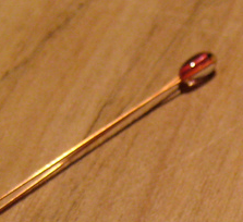
The original fan had three wires and was controlled thermostatically, meaning that a small thermistor would speed up the the fan as the temperature increased. Of course, the standard way of controlling CPU fans these days is with PWM, so he built a circuit which essentially converts the PWM signal from the motherboard into a phantom thermistor. It’s even more impressive that it was able to be done with little more than a MOSFET and a Zener diode.

Unfortunately, there was a catch. The circuit only works one way, meaning the fan speed doesn’t get reported to the motherboard and the operating system thinks the fan has failed. But [Jason] simply disabled the warning and washed his hands of that problem. If you don’t want to use a CPU fan at all, you can always just dunk your entire computer in mineral oil.

High Precision Analog IO With Digital Pins

Reading the temperature of your environment is pretty easy right? A quick search suggests the utterly ubiquitous DHT11, which speaks a well documented protocol and has libraries for every conceivable microcontroller and platform. Plug that into your Arduino and boom, temperature (and humidity!) readings. But the simple solution doesn’t hit every need, sometimes things need to get more esoteric.

The technique summarized by an image from Microchip Appnote AN685

For years we’ve been watching [Edward]’s heroic efforts to build accessible underwater sensing hardware. When we last heard from him he was working on improving the accuracy of his Arduino’s measurements of the humble NTC thermistor. Now the goal is the same but he has an even more surprising plan, throw the ADC out entirely and sample an analog thermistor using digital IO. It’s actually a pretty simple trick based on an intuitive observation, that microcontrollers are better at measuring time than voltage. 

The basic circuit

The circuit has a minimum of four components: a reference resistor, the thermistor, and a small capacitor with discharge resistor. To sense you configure a timer to count, and an edge interrupt to capture the value in the timer when its input toggles. One sensing cycle consists of discharging the cap through the discharge resistor, enabling the timer and interrupt, then charging it through the value to measure. The value captured from the timer will be correlated to how long it took the cap to charge above the logic-high threshold when the interrupt triggers. By comparing the time to charge through the reference against the time to charge through the thermistor you can calculate their relative resistance. And by performing a few calibration cycles at different temperatures ([Edward] suggests at least 10 degrees apart) you can anchor the measurement system to real temperature.

For all the gory details, including tips for how to save every last joule of energy, check out [Edward]’s post and the Microchip appnote AN685 he references. Besides this series [Edward]’s Cave Pearl Project has already yielded an impressive number of Hackday posts. For more great hardware writeups check out a general hardware build for a single sensing node, or the “temperature sensor” [Edward] made with no external parts at all!

Thermistors And 3D Printing

I always find it interesting that 3D printers — at least the kind most of us have — are mostly open-loop devices. You tell the head to move four millimeters in the X direction and you assume that the stepper motors will make it so. Because of the mechanics, you can calculate that four millimeters is so many steps and direct the motor to take them. If something prevents that amount of travel you get a failed print. But there is one part of the printer that is part of a closed loop. It is very tiny, very important, but you don’t hear a whole lot about it. The thermistor.

The hot end and the heated bed will both have a temperature sensor that the firmware uses to keep temperatures at least in the ballpark. Depending on the controller it might just do on-and-off “bang-bang” control or it might do something as sophisticated as PID control. But either way, you set the desired temperature and the controller uses feedback from the thermistor to try to keep it there.

If you print with high-temperature materials you might have a thermocouple in your hot end, but most machines use a thermistor. These are usually good to about 300 °C. What got me thinking about this was the installation of an E3D V6 clone hot end into my oldest printer which had a five-year-old hot end in it. I had accumulated a variety of clone parts and had no idea what kind of thermistor was in the heat block I was using.

Continue reading “Thermistors And 3D Printing”

Building A Better Baby Bottle Boiler

[Sebastian Foerster] hasn’t been at his blog in a while. He and his wife just had twins, so he’s been busy standing waiting for formula or milk to warm up. Being a technical kind of guy, he took a look at the tools currently on the market to do this, analyzed them, and decided instead to do it himself.

[Sebastian] looked to his Nespresso Aeroccino – a milk frother designed to give you hot or cold frothy milk for the top of whatever beverage you decide to put it on top of. It made the milk a bit too hot, 60°C, but once it got to the temperature, it would shut off, so if [Sebastian] could get it to shut off at a lower temperature, he had found the solution!

After taking the Aeroccino apart and going over the circuit, it seemed like a simple design relying on a resistor and NTC (negative temperature coefficient) thermistor connected to an ATTiny44 microcontroller. [Sebastian] didn’t want to have to reprogram the ATTiny, so he looked at the resistor and NTC. The resistor and thermistor create a voltage divider and that voltage is read in by the microcontroller through an analog pin. After looking up some info on the thermistor and replacing the resistor with a potentiometer, [Sebastian] could adjust the shut-off temperature while measuring with a thermometer. When he got the temperature he liked, he reads the value of the potentiometer and then replaces it with a couple of resistors in series.

Now [Sebastian] gets the babies’ bottles ready from fridge to temperature in about 25 seconds. He doesn’t have to worry about keeping an eye on the bottles as they heat up. We’re sure that getting two bottles ready in under a minute is much better on the nerves of new parents than waiting around for ten minutes. For more fun with thermistors, check out our article on resistors controlled by the environment or check out this bluetooth bbq thermometer!

Crossing Wheatstone Bridges

The Wheatstone bridge is a way of measuring resistance with great accuracy and despite having been invented over 150 years ago, it still finds plenty of use today. Even searching for it on Hackaday brings up its use in a number of hacks. It’s a fundamental experimental device, and you should know about it.

Continue reading “Crossing Wheatstone Bridges”

Automatic Resistance: Resistors Controlled By The Environment

Resistors are one of the fundamental components used in electronic circuits. They do one thing: resist the flow of electrical current. There is more than one way to skin a cat, and there is more than one way for a resistor to work. In previous articles I talked about fixed value resistors as well as variable resistors.

There is one other major group of variable resistors which I didn’t get into: resistors which change value without human intervention. These change by environmental means: temperature, voltage, light, magnetic fields and physical strain. They’re commonly used for automation and without them our lives would be very different.

Continue reading “Automatic Resistance: Resistors Controlled By The Environment”

Taming A Variac With A Thermistor

The folks at TOG, Dublin Hackerspace, have a large variac. A variac is a useful device for testing some fault conditions with AC mains powered equipment, it allows an operator to dial in any AC output voltage between zero, and in the case of TOG’s variac, 250V.

Their problem was with such a magnificent device capable of handling nearly 3KW, it presented an inductive load with a huge inrush current at power-on that would always take out the circuit breakers. Breakers come with different surge current handling capabilities, evidently their building is fitted with the domestic rather than the industrial variants.

Their solution was a simple one, they fitted an NTC surge limiter in series with the variac input. This is a thermistor whose resistance falls with temperature. Thus on start-up it presented an extra 12 ohm load which was enough to keep the breaker happy, but soon dropped to a resistance which left the variac with enough juice.

This is a simple fix to a problem that has faced more than one hackerspace whose imperfect lodgings are wired to domestic-grade spec. In a way it ties in neatly with our recent feature on mains safety; making the transformer no longer a pain to use means that it is more likely to be used when it is needed.

Via: TOG, Dublin Hackerspace.