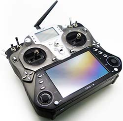
It’s winter, and that means terrible weather and very few days where flying RC planes and helicopters is tolerable. [sjtrny] has been spending the season with RC flight simulators for some practice time. He had been using an old Xbox 360 controller, but that was really unsuitable for proper RC simulation – a much better solution would be to use his normal RC transmitter as a computer peripheral.
The usual way of using an RC transmitter with a computer is to buy a USB simulator adapter that emulates a USB game pad through a port on the transmitter. Buying one of these adapters would mean a week of waiting for shipping, so [sjtrny] did the logical thing and made his own.
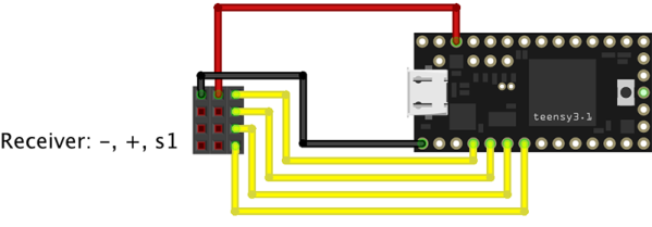
Normally, a USB simulator adapter plugs in to a 3.5mm jack on the transmitter used for a ‘buddy box’, but [sjtrny] had an extra receiver sitting around. Since a receiver simply outputs signals to servos, this provides a vastly simpler interface for an Arduino to listen in on. After connecting the rudder, elevator, aileron, and throttle signals on the receiver to an Arduino, a simple bit of code and the UnoJoy library allows any Arduino and RC receiver to become a USB joystick.
[sjtrny] went through a second iteration of hardware for this project with a Teensy 3.1. This version has higher resolution on the joystick axes, and the layout of the code isn’t slightly terrible. It’s a great project for all the RC pilots out there that can’t get a break in the weather, and is also a great use for a spare receiver you might have sitting around.

 With few exceptions, most of The Hackaday Prize are things we really haven’t seen much of before: base-3 computers that have been relegated to the history books, extremely odd 3D printers, and fancy, new IoT devices are the norm.