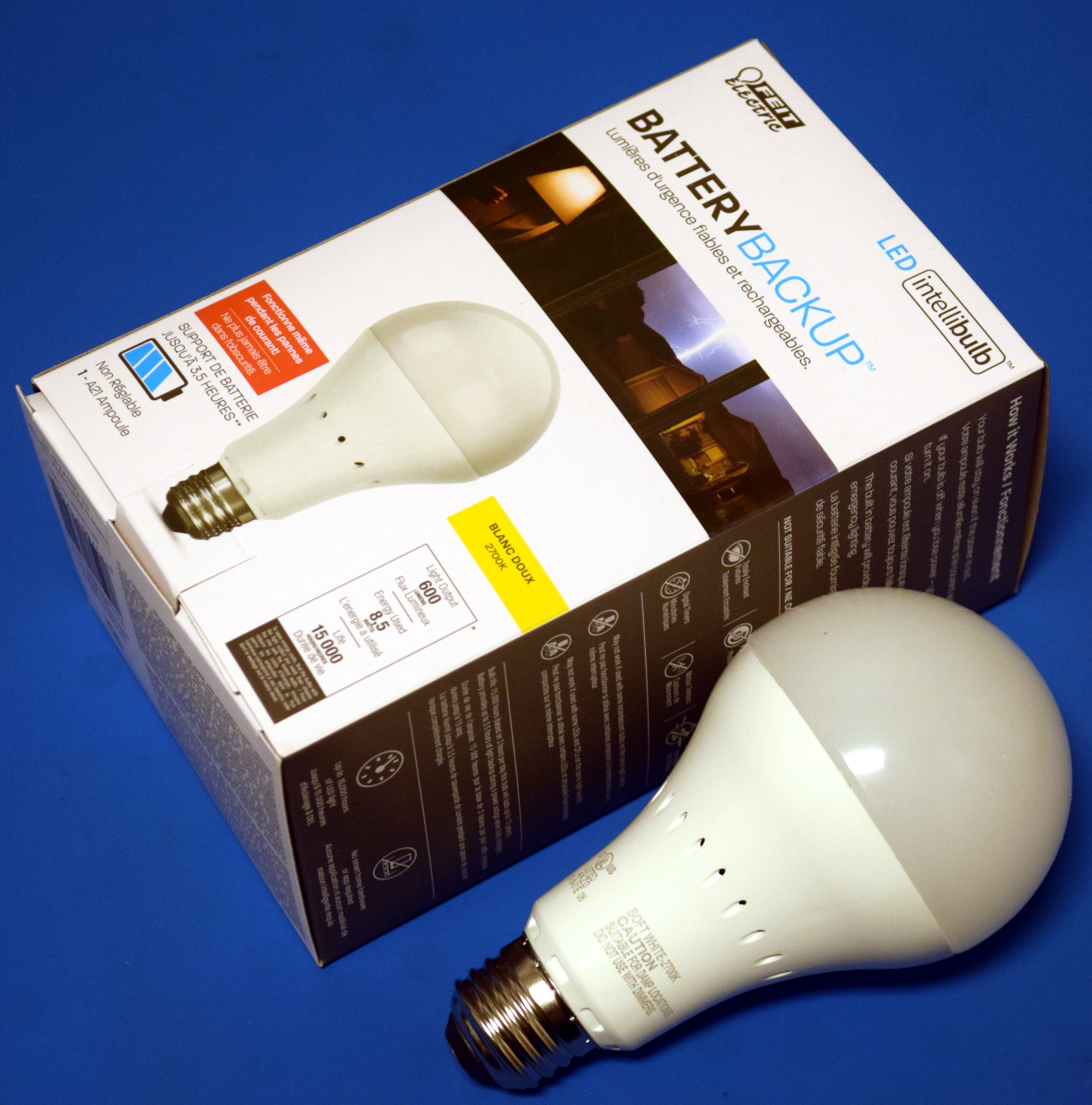
Occasionally you run across a product that you just know is simply too good to be true. You might not know why, but you’ve got a hunch that what the bombastic phrasing on the package is telling you just doesn’t quite align with reality. That’s the feeling I got recently when I spotted the “LED intellibulb Battery Backup” bulb by Feit Electric. For around $12 USD at Home Depot, the box promises the purchaser will “Never be in the dark again”, and that the bulb will continue to work normally for up to 3.5 hours when the power is out. If I could repurpose that to make a tiny UPS for a microcontroller project of my own, it could be even more useful.
 Now an LED light bulb with a battery in the base isn’t exactly rocket science, we can understand the product conceptually at a glance. But as they say, the devil is in the details. The box claims the bulb consumes 8.5 watts, but a battery with enough capacity to run such a load for 3.5 hours would be far too large to fit inside of a light bulb. Obviously there’s more to the story.
On the side of the box, in the smallest font used on the whole package, we get our clue. The bulb drops down to 200 lumens when in battery backup mode, or roughly as bright as a cheap LED flashlight. Now things are starting to come together. Without even opening the device, we can be fairly sure it will contain two separate arrays of LEDs: one low set for battery, and a brighter set to run when the bulb has AC power.
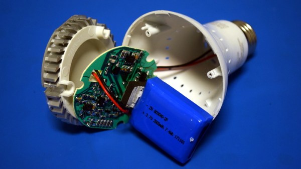
Still, I tend to be of the opinion that anything less than $20 or so is worth cracking open to see what makes it tick. Even if the product itself is underwhelming, there’s a chance the internal components could be useful or interesting. With that in mind, let’s see what’s inside a battery backup light bulb, and what we might be able to do with it.