Vector Network Analyzer Uses SoC FPGA

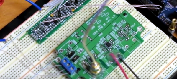
If you are working with AC circuits a vector network analyzer (VNA) is quite handy. As an entry to the InnovateFPGA competition for students, [Evgenii Vostrikov], [Danila Nikiforovskii], and [Daniil Smirnov] created a VNA using a DE10-Nano, high-speed analog to digital and digital to analog converters, and a circulator. Most of the details are in the video below, and on the project’s GitHub page.

The DE10-Nano has a dual-core ARM processor and an Altera FPGA in one package. That allows you to use the CPUs where that makes sense and still leverage the FPGA where you need high performance.

The circulator uses an op-amp to allow the test signal to route to the device under test, while steering any reflected signal back to the device for measurement. The design also uses a lock-in amplifier, something we’ve talked about a few times recently. This allows less expensive converters to generate magnitude and phase information.

Judging by the fan in the video, we suspect the setup gets a little toasty. The GitHub page has a lot of Russian on it, so we aren’t sure how much we could puzzle out since our Russian skills were mostly from watching the Adventures of Moose and Squirrel.

If you are interested in a VNA, they aren’t as expensive as they used to be. Particularly, if you roll your own and already have some things in your junk box.

Continue reading “Vector Network Analyzer Uses SoC FPGA”

Ham Reviews MiniVNA

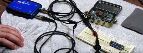
[KB9RLW] wanted to build a vector network analyzer (VNA), but then realized he could buy a ready-made one without nearly the cost it would have been only a few years ago. The network in this case, by the way, is an electrical network, not a computer network. You can use a VNA to characterize components, circuits, antennas, and even feed lines at different frequencies. The miniVNA Pro is economical and can exercise circuits from 1 MHz to 3 GHz. You can see the review in the video below.

There are a few ways to actually create a VNA, but in concept, it is a sweep generator, a detector, and a means to plot the response at each frequency in the sweep. So you’d expect, for example, a resonant frequency to show a peak at resonance and a band reject filter to show a low point.

One of the things interesting about the device is that it uses Java software. That means it doesn’t care much what platform you want to use. The software can show two different plots at once, so [Kevin] hooks it to his 20 meter antenna and shows how it can plot the SWR and impedance around the frequency of interest.

The instrument can be USB powered with the same cable you use to connect the PC. However, it also has an internal rechargeable battery. That battery charges on USB and can operate the device with Bluetooth. We can imagine that being handy when you want to climb up a tower and connect it directly to an antenna as long as you stay in Bluetooth range of the PC. There’s also a phone app, so you can go that route, if you prefer and [Kevin] shows the device working with Android. Of course, you could probably rig a Raspberry Pi on your belt and then use WiFi to let someone on the ground remote desktop in to run measurements. A lot of possibilities.

If you want to roll your own, that’s possible, of course. If you want to get by a bit cheaper, there are less expensive options.

Continue reading “Ham Reviews MiniVNA”

Putting A Poor Man’s Vector Analyzer Through Its Paces

If anything about electronics approaches the level of black magic, it’s antenna theory. Entire books dedicated to the subject often merely scratch the surface, and unless you’re a pro with all the expensive test gear needed to visualize what’s happening, the chances are pretty good that your antenna game is more practical than theoretical. Not that there’s anything wrong with that — hams and other RF enthusiasts have been getting by with antennas that work without really understanding why for generations.

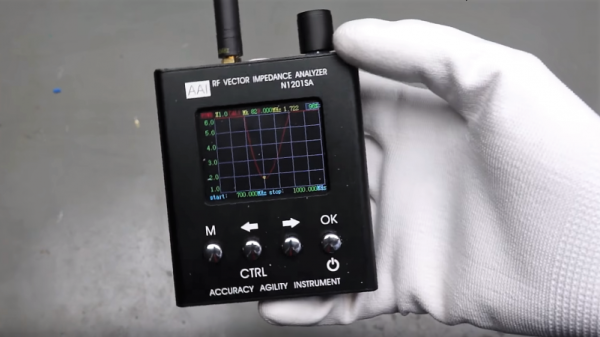
But we’re living in the future, and the tools to properly analyze antenna designs are actually now within the means of almost everyone. [Andreas Spiess] recently reviewed one such instrument, the N1201SA vector impedance analyzer, available from the usual overseas sources for less than $150. [Andreas]’s review does not seem to be sponsored, so it seems like we’re getting his unvarnished opinion; spoiler alert, he loves it. And with good reason; while not a full vector network analyzer (VNA) that will blow a multi-thousand dollar hole in your wallet, this instrument looks like an incredible addition to your test suite. The tested unit works from 137 MHz to 2.4 GHz, so it covers the VHF and UHF ham bands as well as LoRa, WiFi, cell, ISM, and more. But of course, [Andreas] doesn’t just review the unit, he also gives us a healthy dose of theory in his approachable style.

[The guy with the Swiss accent] has been doing a lot of great work these days, covering everything from how not to forget your chores to reverse engineering an IoT Geiger counter. Check out his channel — almost everything he does is worth a watch.

Continue reading “Putting A Poor Man’s Vector Analyzer Through Its Paces”

Network Analysers: The Electrical Kind

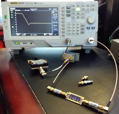
Instrumentation has progressed by leaps and bounds in the last few years, however, the fundamental analysis techniques that are the foundation of modern-day equipment remain the same. A network analyzer is an instrument that allows us to characterize RF networks such as filters, mixers, antennas and even new materials for microwave electronics such as ceramic capacitors and resonators in the gigahertz range. In this write-up, I discuss network analyzers in brief and how the DIY movement has helped bring down the cost of such devices. I will also share some existing projects that may help you build your own along with some use cases where a network analyzer may be employed. Let’s dive right in.

Network Analysis Fundamentals

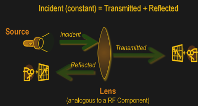
As a conceptual model, think of light hitting a lens and most of it going through but part of it getting reflected back.

The same applies to an electrical/RF network where the RF energy that is launched into the device may be attenuated a bit, transmitted to an extent and some of it reflected back. This analysis gives us an attenuation coefficient and a reflection coefficient which explains the behavior of the device under test (DUT).

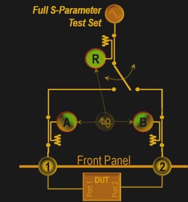
Of course, this may not be enough and we may also require information about the phase relationship between the signals. Such instruments are termed Vector Network Analysers and are helpful in measuring the scattering parameters or S-Parameters of a DUT.

The scattering matrix links the incident waves a1, a2 to the outgoing waves b1, b2 according to the following linear equation: \begin{bmatrix} b_1 \\ b_2 \end{bmatrix} = \begin{bmatrix} S_{11} & S_{12} \\ S_{21} & S_{22} \end{bmatrix} * \begin{bmatrix} a_1 \\ a_2 \end{bmatrix} .

The equation shows that the S-parameters are expressed as the matrix S, where and denote the output and input port numbers of the DUT.

This completely characterizes a network for attenuation, reflection as well as insertion loss. S-Parameters are explained more in details in Electromagnetic Field Theory and Transmission Line Theory but suffice to say that these measurements will be used to deduce the properties of the DUT and generate a mathematical model for the same.

General Architecture

As mentioned previously, a simple network analyzer would be a signal generator connected and a spectrum analyzer combined to work together. The signal generator would be configured to output a signal of a known frequency and the spectrum analyzer would be used to detect the signal at the other end. Then the frequency would be changed to another and the process repeats such that the system sweeps a range of frequencies and the output can be tabulated or plotted on a graph. In order to get reflected power, a microwave component such as a magic-T or directional couplers, however, all of this is usually inbuilt into modern-day VNAs.
Continue reading “Network Analysers: The Electrical Kind”

Handheld Network Analyzer Peek Inside

[Shahriar] recently posted a review of a 6.8 GHz network analyzer. You can see the full video — over fifty minutes worth — below the break. The device can act as a network analyzer, a spectrum analyzer, a field strength meter, and a signal generator. It can tune in 1 Hz steps down to 9 kHz. Before you rush out to buy one, however, be warned. The cost is just under $2,000.

That sounds like a lot, but test gear in this frequency range isn’t cheap. If you really need it, you’d probably have to pay at least as much for something equivalent.

[Shahriar] had a few issues to report, but overall he seemed to like the device. For example, setting the step size too broad can cause the spectrum analyzer to miss narrow signals.

If your needs are more modest, we’ve covered a much simpler (and less expensive) unit that goes to 6 GHz. If you need even less, an Arduino can do the job with a good bit of help. The Analog Discovery 2 also has a network analyzer feature, along with other tools at a more affordable cost, too. Of course, that’s only good to 10 MHz.

Continue reading “Handheld Network Analyzer Peek Inside”