GUI Window Manager On An AVR Chip

avr-window-manager-gui

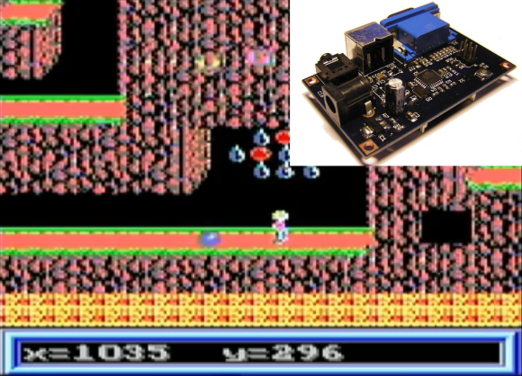
This project is reminiscent of the old days when window managers were an amazing new idea. The difference is that this window-based GUI is running on an ATmega1284 microcontroller. But the behavior and speed of the interface is pretty much exactly what you’d expect if working on an early 90’s home computer. It even uses a mouse as input.

So how is this even possible? The key to the project is a serial to VGA module which handles the heavy lifting involved with generating a VGA signal. We featured one of [Andrew’s] past projects which used an AVR chip to generate the VGA signal. But that doesn’t leave nearly enough cycles to implement something like a window manager, not to mention the fact that it got nowhere near the resolution shown here.

He uses a serial mouse with an RS-232 converter chip to interact with the windows. This is best shown in his video after the break. He’s able to generate and interact with new windows. He even implemented a set of rudimentary controls which allow him to adjust the theme of the windows and drive the audio playback feature included on that VGA controller he’s using.

Continue reading “GUI Window Manager On An AVR Chip”

AVR VGA Generator

avr-vga-generator

This simple circuitry makes up the hardware for [Andrew’s] AVR-based VGA generator. He managed to get an ATmega1284 to output a stable VGA signal. Anyone who’s looked into the VGA standard will know that this is quite an accomplishment. That’s because VGA is all about timing, and that presented him with a problem almost immediately.

The chip is meant to run at a top speed of 20 MHz. [Andrew] did manage to get code written that implemented the horizontal and vertical sync at this speed. But there weren’t enough clock cycles left to deal with frame buffering. His solution was to overclock the chip to 25 MHz. We assume he chose that because he had a crystal on hand, because we think it would have been easier to use a 25.174 MHz crystal which is one of the speeds listed in the specification.

Red, green, and blue each get their own two-bit range selected via a set of resistors for a total of 64 colors. As you can see in the video after the break, the 128×96 pixel video is up and running. [Andrew] plans to enlarge the scope of the project from here to make it more versatile than just showing standard images. The code (written in assembly) is available at his GitHub repository.

Continue reading “AVR VGA Generator”

Veronica 6502 Computer Reaches Hello World Stage

veronica-hello-world

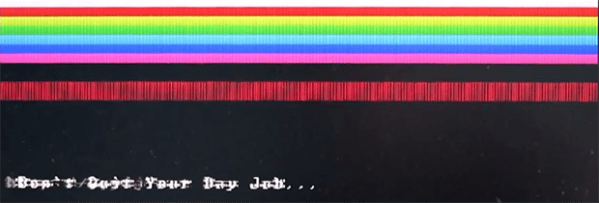
The screenshot on the right shows [Quinn Dunki’s] computer project displaying a Hello World program. Well, it’s only showing the word Hello right now, but the concept is the same. This proves that native 6502 code is running on the processor and reliably outputting data through its VGA hardware. That’s a welcome achievement after watching so much work go into this project.

But with anything this complex you can’t expect to make progress without finding bugs. And this step in the journey had a pretty big one in store for [Quinn]. After writing the assembly code and loading it into the machine she was dismayed to find that there were dropped characters all over the place. Now she shows a screenshot and says it’s easily recognizable as a race condition — proving she has a bigger brain than us.

The problem is a pair of uninterruptible processes running on the same AVR chip (part of the GPU she built). They are fighting with each other for control of the processor cycles and she fixed it by making the daughter board seen in the image above. It moves one of the time-critical processes out of that single AVR chip to fix the issue by using an IDT7200L FIFO SRAM chip.

Veronica VGA Board Finalized

veronica-vga-board-finalized

The latest update in the Veronica 6502 computer project is this finalized VGA board which now has a home in the machine’s backplane.

We’ve been glued to the updates [Quinn Dunki] has been posting about the project for many months now. Getting the GPU working proved to take quite a bit of time, but we learned a ton just by following along. The video output had humble beginnings way back in March. That breadboarded circuit got complicated very quickly and that was before it was even interfaced with the CPU. As you can see from the image above, etching and populating the GPU board really cleans up the build. We’re sure it’s robust enough to move around at this point. We wonder if she’s planning on showing it off at a Maker Faire or another geeky gathering?

It really has become clear how wise [Quinn] was to design a backplane board early on. It plays right into the modular concept. She was even smart enough to include that SIL pin header on the near side of the board which was used heavily while prototyping this video module.

Adding A SCART Input To A Console VGA Converter

If you’re working with a CGA, EGA, or RGB gaming system this inexpensive board does a great job of converting the signal to VGA so that you can play using a modern display. But what if you have a SCART connector as an output? That’s the situation in which [EverestX] found himself so he hacked in SCART support.

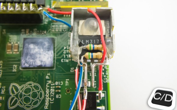
The first step is to source a female SCART connector. He grabbed a coupler off of eBay and cracked it open, yielding two connectors. Now comes the wiring and you may have already noticed that there’s a lot more going on here than the color channels, sync signal, and ground. Technically that’s all you really need to make this happen, but the results will not be good. First off, the sync signal for SCART tends to be rather awful. That’s where the blue breakout board comes into play. [EverestX] used an LM1881 to grab the composite sync (yes, composite sync, not component sync) signal as a feed for the VGA converter. He also added in an audio jack for the sound that is coming through the connector.

Fortifying Veronica’s VGA Output

[Quinn Dunki] just moved to a new work space and had to pack up her homebrew computer project — called Veronica — in the process. She just unboxed it again and decided now was a good time to fortify the VGA display hardware. It wasn’t in the greatest of shape, since everything for the initial video tests had been built on a breadboard. The transition to protoboard ended up turning out just swell.

One of the thing’s that we like best about [Quinn’s] hacks is that she documents her failures (or perhaps we should just call them hiccups?) just as much as she does her successes. This is not a small thing. We understand, because our own screw-ups don’t usually get photographed due to our raging need to just make the frakking thing work.

Once she had moved all the components to the new board the circuit was amazingly organized. Since she’s doing high-speed switching with the VGA signals it was important to keep the lines as short and straight as possible, hence the SRAM stack seen above. But when it was first fired up she had a jumble of only-somewhat-organized color stripes. It turns out that she had forgotten to change the color register in the AVR code, the color lines were hooked up in the wrong order, and the switch mode supply was injecting noise into the system. But thanks to her documentation of these issues we’ll know what to do when we find ourselves in a similar situation.

Moving An FPGA Project From VGA To DVI-D

It’s fairly easy to create VGA with an FPGA using a simple R/2R DAC. As [Mike] points out, this requires a lot of IO pins, and many development boards only support 8 bit VGA. Analog VGA is being replaced with DVI-D and HDMI on many devices nowadays, so it would be nice to port projects from VGA to DVI-D.

To address this, he’s come up with a simple DVI-D implementation in VHDL. The result converts RGB and sync data for VGA into DIV-D. Since DVI-D and HDMI both use the same signals for video, this can be connected to either input on a monitor or TV.

This implementation is shown displaying a test pattern on the Pipistrello development board, which features a Spartan 6 LX45 FPGA, but the project was written to be portable to other vendor’s FPGAs. With the right connector and a fast enough clock speed, this project should help move a project from 8 bit VGA to glorious 32 bit color.