Kirby Sucks, Literally

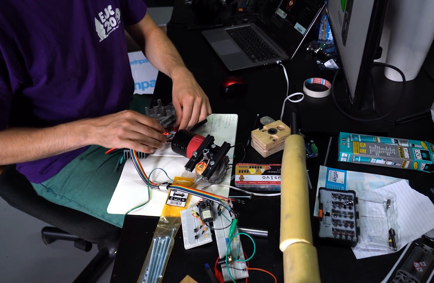
What’s common between one of the most legendary video game characters of all time and a fume extractor ? They both suck. [Chris Borge] is not an electronics hobbyist and only does some occasional soldering. This made his regular fume extractor bulky and inconvenient to position where needed. What could serve him better would be a small extractor that could be attached to a clip or an arm on his helping hand accessory. Being unable to find an off-the-shelf product or a suitable 3d printed design that he liked, he built the Kirby 40mm Fume Extractor.

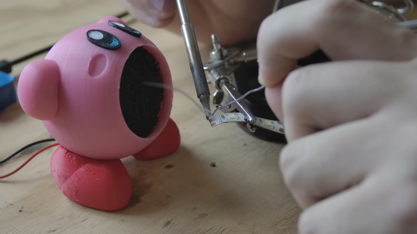
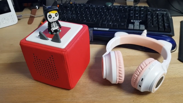
His initial idea was for a practical design more suited to his specific needs. But somewhere along the way, the thought of a Kirby fan popped up in his head, and it was too good an idea to pass up. Several Kirby fan designs already existed, but none that satisfied [Chris]. Getting from paper sketch to CAD model required quite an effort but the result was worth the trouble, and the design was quite faithful to the original character features. The main body consists of two halves that screw together, and an outlet grill at the back. The body has space for a 40 mm fan and a 10 mm charcoal filter in the front. The wires come out the back, and connect directly to a power supply barrel jack. Arms and eyes are separate pieces that get glued to the body. The feet glue to an intermediate piece, which slides in a dove tail grove in the body. This allows Kirby to be tilted at the right position for optimum smoke extraction.

While Kirby served the purpose, it still didn’t meet the original requirement of attaching to a clip or arm on the helping hand. So [Chris] quickly designed a revised, no-frills model which is essentially a square housing to hold the fan and the filter. It has a flexible stand so it can be placed on a bench. And it can also be attached to the helping hand, making it a more utilitarian design. This design has the charcoal filter behind the fan, but he also has a third design for folks who prefer to have the filter at the front.

He now had a more useful, practical fume extractor, but he couldn’t bring himself to discard his original Kirby. So he printed a couple more 3D parts so that Kirby could fit the end of his vacuum cleaner hose. Now, Kirby sits on his bench, and helps suck up all the bits and bobs of trash on his workbench. We’re sure Kirby is quite pleased with his new role.

Continue reading “Kirby Sucks, Literally”

Impressive Sawdust Briquette Machine

When you are a life long carpenter with an amazing workshop, you’re going to make a lot of saw dust, and managing its collection and storage poses quite a challenge. [Russ] from [New Yorkshire Workshop] built an impressive Briquette press to handle the problem.

It’s a hydraulic press that ingests  saw dust and spits out compressed briquettes ready for fueling his rocket mass heater. The build starts with a batch of custom, laser cut steel parts received from Fractory. The heart of the machine is a 300 mm stroke hydraulic cylinder with a beefy 40 mm rod. The cylinder had to be taken apart so that the laser cut mounting flanges could be welded, slowly so as not to deform the cylinder. The intake feed tube was cut from a piece of 40 mm bore seamless tube. A window was cut in the feed tube and funnel parts were welded to this cutout. The feed tube assembly is then finished off with a pair of mounting flanges. The feed tube assembly is in turn welded to the main feed plate which will form the base of the saw dust container. The hydraulic cylinder assembly is mated to the feed tube assembly using a set of massive M10 high tensile class 10.9 threaded rods. The push rod is a length of 40 mm diameter mild steel bar stock, coupled to the hydraulic cylinder using a fabricated coupling clamp. On the coupling clamp, he welded another bracket on which a bolt can be screwed on. This bolt helps activate the limit switches that control the movement of the hydraulic cylinder and the feed motor. Continue reading “Impressive Sawdust Briquette Machine”

Blinky Business Card Plays Snake And Connect Four

There’s no better way to introduce yourself than handing over a blinky PCB business card and challenging the recipient to a game of Connect Four. And if [Dennis Kaandorp] turns up early for a meeting, he can keep himself busy playing the ever popular game of Snake on his PCB business card.

The tabs are 19 mm long and 4 mm wide.

Quite wisely, [Dennis] kept his design simple, and avoided the temptation of feature creep. His requirements were to create a minimalist, credit card sized design, with his contact details printed on the silk legend, and some blinky LED’s.

The tallest component on such a design is usually the battery holder, and he could not find one that was low-profile and cheap. Drawing inspiration from The Art of Blinky Business Cards, he used the 0.8 mm thin PCB itself as the battery holder by means of flexible arms.

Connect-Four is a two player game similar to tic-tac-toe, but played on a grid seven columns across and six rows high. This meant using 42 dual-colour LED’s, which would require a large number of GPIO pins on the micro-controller. Using a clever combination of matrix and charlieplexing techniques, he was able to reduce the GPIO count down to 13 pins, while still managing to keep the track layout simple.

It also took him some extra effort to locate dual colour, red / green LED’s with a sufficiently low forward voltage drop that could work off the reduced output resulting from the use of charlieplexing. At the heart of the business card is an ATtiny1616 micro-controller that offers enough GPIO pins for the LED matrix as well as the four push button switches.

His first batch of prototypes have given him a good insight on the pricing and revealed several deficiencies that he can improve upon the next time around. [Dennis] has shared KiCad schematic and PCB layout files for anyone looking to get inspired to design their own PCB business cards.

Continue reading “Blinky Business Card Plays Snake And Connect Four”

A Medieval Gothic Monastery Built Using CAD / CAM

Just because you’re a monk doesn’t mean you can’t use CAD. The Carmelite monks of Wyoming are building a grandiose Gothic Monastery, and it’s awe inspiring how they are managing to build it.

The Carmelite monks needed a new, larger monastery to house their growing numbers, and found a parcel of land near Meeteetse Creek in Wyoming. The design of their new Gothic monastery was outsourced to an architectural firm. Gothic architecture is characterised by key architectural elements such as pointed arches, large stained glass windows, rib vaults, flying buttresses, pinnacles and spires, elaborate entry portals, and ornate decoration.

After some research, the monks settled on using Kansas Silverdale limestone for the monastery. Cutting and carving the elaborate stone pieces required for such a project, within time and cost constraints, could only be achieved using CNC machines. Hand carving was ruled out as it was a very slow process, would cost a whole lot more, and it wouldn’t be easy to find the artisans for the job. So when it came to shortlisting vendors for the vast amount of stone cutting and carving required for construction, the monks found themselves alarmed at how prohibitively expensive it would turn out to be.

Continue reading “A Medieval Gothic Monastery Built Using CAD / CAM”

Robotic Acrobot Aces The Moves

[Daniel Simu] is a performance artist, among many other things, and does acrobatic shows, quite often with a partner “flyer”. Training for his acts gets interrupted if his flyer partner is not available due to travel, injury or other reasons. This prompted him to build Acrobotics — a robotic assistant to make sure he can continue training uninterrupted.

He has some electronics and coding chops, but had to teach himself CAD so that he could do all of the design, assembly and programming himself. Acrobotics was developed as part of a Summer Sessions residency at V2_ (Lab for the Unstable Media) at Rotterdam in 2022.

The design is built around a mannequin body and things are quite simple at the moment. There are only two rotational joints for the arms at the shoulder, and no other articulations. Two car wiper motors rotate the two arms 360 deg in either direction. Continuous rotation potentiometers attached to the motors provide position feedback.

An ESP32 controls the whole thing, and the motors get juice via a pair of BTS7960 motor drivers. All of this is housed in a cage built from 15 mm aluminium extrusion and embedded in the torso of the mannequin. [Daniel] doesn’t enlighten us how the motor movements are synchronized with the music, but we do see a trailing cable attached to the mannequin. It’s likely the cable could be for power delivery, as well as some form of data or timing signals.

He’s working on the next version of the prototype, so we hope to see improved performances soon. There’s definitely scope for adding a suite of sensors – an IMU would help a lot to determine spatial orientation, maybe some ultrasonic sensors, or a LiDAR for object detection or mapping, or additional articulated joints at the elbows and wrists. We gotta love “feature creep”, right ?

Check out the two videos after the break – in the first one, he does an overview of the Acrobotics, and the second one is the actual performance that he did. Robot or not, it’s quite an amazing project and performance.
CAVEAT : We know calling this a “robot” is stretching the definition, by a lot, but we’re going to let it slip through.

Continue reading “Robotic Acrobot Aces The Moves”

CUTTING CABLES CURES TANGLED CORD CHAOS

The Toniebox is a toy that plays stories and songs for kids to listen to. Audio content can be changed by placing different NFC enabled characters that magnetically attach to the top of the toy. It can play audio via its built-in speaker or through a wired headphone connected to the 3.5 mm stereo jack. Using the built in speaker could sometimes be quite an irritant, especially if the parents are in “work from home” mode. And wired headphones are not a robust alternative, specially if the kid likes to wander around or dance while listening to the toy. We guess the manufacturers didn’t get the memo that toddlers and cables don’t mix well together. Surprisingly, the toy does not support Bluetooth output, so [g3gg0] hacked his kids Toniebox to add Bluetooth audio output.

[g3gg0] first played with the idea of transmitting audio via an ESP32 connected to the I²S interface, running a readily available A2DP library. While elegant, it is a slightly complex and time consuming solution. Using the ESP32 would also have affected the battery life, given the ESP32’s power hungry nature. Continue reading “CUTTING CABLES CURES TANGLED CORD CHAOS”

An ESP32 Development Board For Sailors

[Matti Airas] wanted to have a better electronics platform for making his boat smarter, more connected, and safer. He found traditional marine electronics expensive and not suited for hacking and tinkering. There was also the issue of lack of interoperability between device generations from the same supplier and between different brands. This led him to design the Sailor Hat with ESP32 — a marine specific, open source hardware development board.

Applications include all kinds of sensor and control interfaces for the boat, such as measurement of fuel or water level, engine RPM, anchoring chain length counter, or setting up smart lighting or smart refrigeration control. The board is designed to work with the traditional NMEA 2000 standard, as well as with Signal K. NMEA 2000 is standardized as IEC 61162-3, but isn’t open source or free. Signal K, on the other hand, is free and open source, and can co-exist alongside NMEA 2000.

The marine environment can be pretty harsh with extremes of temperature, rain, humidity, condensation and vibration. Boats, just like automobiles, have a notoriously noisy electrical environment and [Matti] has paid special attention to noise and surge suppression throughout the board. The board can work with either 12 V or 24 V bus systems since the on board DC-DC converter is rated up to 32 V input. Connections between the board and the outside world need to be very robust, so it is designed to accept various types of connectors depending on how robust you want it to be.

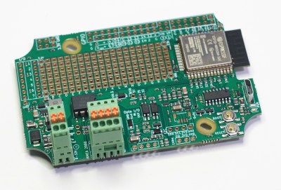
The Sailor Hat is based around a standard ESP32-WROOM-32 module. Interfaces include a CAN bus transceiver, opto-coupled input and output, I2C, 1-wire and QWIIC interfaces, USB Micro-B programming conector, plus a couple of buttons and LEDs. All of the ESP32 GPIO pins are terminated on a GPIO header, with jumper options to disable terminations to the standard interfaces and instead route them to the GPIO header as needed. Additionally, there’s a generous prototyping area to add additional hardware to the board. Hardware design files are hosted on the project repository on GitHub.

On the software side, there are several frameworks that can be used, with PlatformIO, SensESP, ESPHome and Visual Studio Code being the recommended choices. Or you could use any of the widely available SDK’s for the ESP32 platform — Espressif SDK, Arduino Core for ESP32, MicroPython, NodeMCU or Rust.

[Matti]’s NMEA 2000 USB gateway example is a good way to get a grip on hardware assembly and software installation required to build a practical project using the Sailor Hat. The board is designed to withstand a harsh electrical environment. But it’s mechanical installation obviously requires greater care if it has to survive marine applications. The Sailor Hat can be installed in commonly available, 100x68x50 mm or larger plastic waterproof enclosures, rated for IP65 or higher. The bulkhead connectors and cable glands also need to be appropriately rated, and the enclosure may possibly need a IP68 rated ventilation plug to take care of environmental cycling within the enclosure.