Easy USB‑C Power For All Your Devices

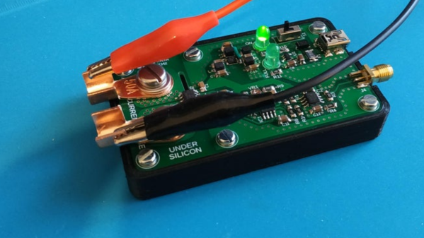
[Mansour Behabadi] wanted to harness the high power capability of USB-C using as simple a hardware design as possible. After some research and experimental prototyping, he designed the fpx — an easy to use USB‑C power delivery board. The fpx is an improved follow up to his earlier USB PD project fabpide2 which we featured some time back. However, practical implementation of the USB PD protocol can be a bed of thorns. Negotiating power delivery usually requires a dedicated PD controller coupled with a micro-controller for user control.

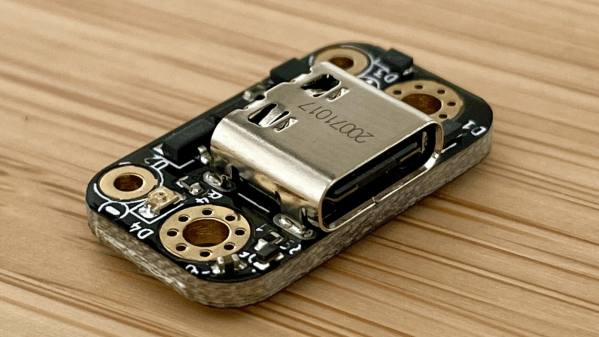
With USB PD, a USB-C port can be configured as either a source, a sink, or both and allows connected devices to negotiate up to 100 W (20 V, 5 A) of power. The fpx is based around the popular STUSB4500 PD controller, which does most of the PD heavy lifting. To program the STUSB4500, he used an ATtiny 816 micro-controller, whose UPDI programming and debugging interface consumes lower board real estate.

However, what’s a little bit different is the way the fpx is programmed — by sending binary black and white flashes from any device that can display a web page. Using light isn’t a particularly new way of programming. We’ve seen it used almost a decade back by WayneAndLayne for their Blinky PoV projects, and later by the Electric Imp’s BlinkUp app. The fpx uses a similar method to read flashes of light from a screen which are picked up by a photo-transistor connected to the ATtiny. The ATtiny then communicates with the STUSB4500 over I2C. This eliminates the requirement for special software or an IDE for programming and doesn’t need any physical cable connection. Check out [Mansour]’s blog post where he walks us through the details of how he managed to wrangle the optical programming challenge.

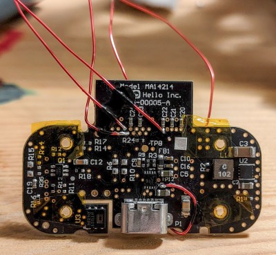
Many of the commercially available USB PD decoy/detector/trigger boards use either solder jumpers or a switch with an RGB LED to adjust Power Delivery Output (PDO). [Mansour]’s method may be a little more robust and reliable. The STUSB4500 can store two separate PDO values and can negotiate with a source according to its capability. If the source cannot offer either of these options, the fpx can either request for a minimal 5 V / 100 mA setting, or disable the output. The fpx is an open source project, accessible on Github. Check out the video after the break for an overview of the fpx.

Continue reading “Easy USB‑C Power For All Your Devices”

Smart Pet Feeder Is Well Engineered

Having pets can sometimes be more demanding than raising kids. Pet owners obviously love and adore their pets, but anything that can be done to reduce their “chores” can be a welcome relief. One big pain point is feeding them at the right time and in the right amount, especially when it comes to cats. As the saying goes, “Dogs have Masters, Cats have Staff! ”

[Sebastian] had had it with his cat [Strachu] nagging him at odd hours for food. Luckily, [Sebastian] is a skilled maker, and his IoT Cat Feeder is not only practical, but also extremely well engineered. He designed and built it from scratch, and the beautiful, final version shows the effort he put in to it. His requirements were quite straightforward. It had to integrate with his home automation system, had to dispense food based on a regular schedule, send him a notification at other times of the day when the feeder detected the cat so he could decide if the cat deserved a special treat or not, and allow him to manually dispense cat food. Finally, he also wanted it to be easy to take apart so he could wash the parts that are in contact with food.

For the electronics, [Sebastian] designed a custom board to hold the ESP12F module and all the other associated parts. Everything, other than the stepper motor is mounted on the PCB. A PIR sensor is used for cat detection. A piezo buzzer lets the cat know that food is ready. A push button can be used to manually dispense food when required. The ESP8266 is flashed with ESPhome which allows control via simple yet powerful configuration files and control them remotely through the Home Assistant addon. If you’re interested in taking a look under the hood, [Sebastian] walks through some of the key code blocks on the ESP side, as well as the various configuration and setting options for the Home Assistant.

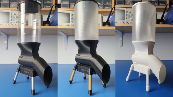
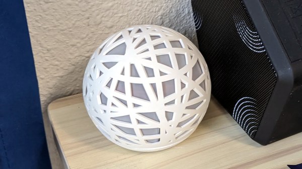
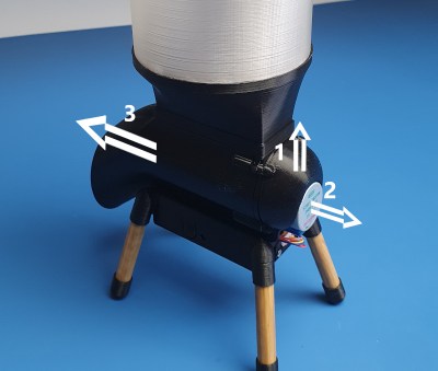
But by far the most effort he needed was in getting the mechanical design perfected. He had to go through several rounds of prototype iterations – after all, his cat deserved the very best in feeder design. The basic parts of the design are simple – a stepper motor drives an auger that pushes the cat food from the main container and deposits it in the bowl. Check out the detailed assembly instructions and pictures on his blog. The best part of his design is how easy it is to take it apart the feeder for cleaning. The stepper motor is held in place by a snap fit end piece without using any screws. The main body then just slides out from the top of the electronics box. Check out [Sebastian]’s cat feeder video after the break for details.

If this design makes you hanker to make one for your cat too, head over to his blog post and provide your mail address and [Sebastian] will send all the files for the project.

If your cat isn’t satisfied with dry food nuggets, you probably ought to build this Automated Cat Feeder That Handles Wet Food With Aplomb.

Continue reading “Smart Pet Feeder Is Well Engineered”

Portrait Of A Digital Weapon

Over the years, artists have been creating art depicting weapons of mass destruction, war and human conflict. But the weapons of war, and the theatres of operation are changing in the 21st century. The outcome of many future conflicts will surely depend on digital warriors, huddled over their computer screens, punching on their keyboards and maneuvering joysticks, or using devious methods to infect computers to disable or destroy infrastructure. How does an artist give physical form to an unseen, virtual digital weapon? That is the question which inspired [Mac Pierce] to create his latest Portrait of a Digital Weapon.

[Mac]’s art piece is a physical depiction of a virtual digital weapon, a nation-state cyber attack. When activated, this piece displays the full code of the Stuxnet virus, a worm that partially disabled Iran’s nuclear fuel production facility at Natanz around 2008. Continue reading “Portrait Of A Digital Weapon”

Garage Door Controller Gets The IoT Treatment

[TheStaticTurtle] built a custom controller for automating his garage doors. He wanted to retain the original physical button and RF remote control interfaces while adding a more modern wireless control accessible from his internet connected devices. Upgrading an old system is often a convoluted process of trial and error, and he had to discard a couple of prototype versions which didn’t pan out as planned. But luckily, the third time was the charm.

The original door-closer logic was pretty straightforward. Press a button and the door moves. If it’s not going in the desired direction, press the button once again to stop the motor, and then press it a third time to reverse direction. With help from the user manual diagrams and a bit of reverse-engineering, he was able to get a handle on how to plan out his add-on controller to interface with the old system.

There are many micro-controller options available these days when you want to add IoT to a project, but [TheStaticTurtle] decided to use the old faithful ESP8266 as the brains of his new controller. For his add-on board to work, he needed to detect the direction in which the motor was turning, and detect the limit switches when the door reached end of travel in either direction. Finally, he needed a relay contact in parallel with the activation button to send commands remotely.

To sense if the motor was moving in the “open” or “close” direction, he used a pair of back-to-back opto-couplers in parallel with the motor terminals. He connected another pair of opto-couplers across the two end-limit switches which indicated when the door was fully open or closed, and shut off the motor supply. Finally, a GPIO from the ESP8266 actuates a relay to send the door open and close commands. The boards were designed in EasyEDA and with a quick turnaround from China, he was able to assemble, test and debug his boards pretty quickly.

The code was written using the Arduino IDE and connects the ESP8266 to the MQTT server running on his home automation computer. The end result is a nice dashboard with three icons for open, close and stop, accessible from all the devices connected to his home network. A 3D printed enclosure attaches outside the original control box to keep things tidy. Using hot melt glue as light pipes for the status LED’s is a pretty nifty hack. If you are interested in taking a deeper look at the project, [TheStaticTurtle] has posted all resources on his Github repository.

High Current Measurement Probe For Oscilloscopes

A decent current measurement sensor ought to be an essential part of every hacker’s workbench. One that is capable of measuring DC, as well as low and high frequencies with reasonable accuracy. And bonus credits if it can also withstand high bus voltages – such as those found in mains utility or electric vehicle work. [Undersilicon] couldn’t find one that ticked all the boxes, so he built an ACS730 based AC/DC current probe capable of measuring up to 25 A at frequencies up to 1 MHz.

Allegro Microsystems has a wide offering of current sensor IC’s. The ACS730 features a -3 dB bandwidth of 1 MHz, and -1 dB bandwidth of 500 kHz. Since it is galvanically isolated, it can be used in AC mains applications up to 297 Vrms and for DC up to 420 V. And as he intended to use it as an oscilloscope accessory, the analog output suited the application nicely. A pair of precision op-amps provide the voltage output scaled to 100 mV/A. The board is powered off a 1000 mAh LiPo battery that can run the sensor for about 15 ~ 20 hours. The power supply section consists of a charge circuit for the LiPo, and a split rail dual output power supply converter for the op-amps.

The ACS730 has a 2.5 V output when measured current is zero, and is scaled for 40 mV/A. This gives an output voltage swing from -0.5 V for -50 A to +4.5 V for +50 A. This is where the AD823ARZ dual 16 MHz, Rail-to-Rail FET Input Amplifiers step in. One pair is used to obtain a 2.5 V reference from the 5 V supply, and also to buffer the analog output from the ACS730. The second pair subtracts the 2.5 V offset, and applies a gain of 2.5 to get the 100 mV/A output. Dual power supply for the op-amps comes from a TPS65133 Split-Rail Converter, ±5V, 250mA Dual Output Power Supply. Lastly, LiPo charging is handled by the MCP73831 Single Cell, Li-Ion/Li-Polymer Charge Management Controller.

Initial testing of direct currents has shown fairly accurate performance. But he’s observed some noise when measuring currents below 1 A which requires some debugging to figure out the source. [Undersilicon] has provided the CAD files for both the PCB and 3D printed enclosure, giving you access to everything you need to build one yourself. If you’re looking for something a bit more heavy duty, you might be interested in this +/-50 A, 1.5 MHz sensor encased in concrete.

Orphaned IoT Sleep Tracker Resurrected As An Air Quality Monitor

If you have a Hello Sense sleep tracking device lying around somewhere in your drawer of discards, it can be brought back to life in a new avatar. Just follow [Alexander Gee]’s instructions to resurrect the Hello Sense as an IoT air quality data-logger.

In 2014, startup “Hello” introduced the Sense, an IoT sleep tracking device with a host of embedded sensors, all wrapped up in a slick, injection molded spherical enclosure. The device was quite nice, and by 2015, they had managed to raise $21M in funding. But their business model didn’t seem sustainable, and in 2017, Hello shut shop. Leaving all the Sense devices orphaned, sitting dormant in beautifully designed enclosures with no home to dial back to.

The original Sense included six sensors: illumination, humidity, temperature, sound, dust / particulate matter on the main device, and motion sensing via a separate Bluetooth dongle called the Pill. [Alexander] was interested in air quality measurements, so only needed to get data from the humidity/temperature and dust sensors. Thankfully for [Alexander], a detailed Hello Sense Teardown by [Lindsay Williams] was useful in getting started.

The hardware consisted of four separate PCB’s — power conditioning, LED ring, processor, and sensor board. This ensured that everything could be fit inside the orb shaped enclosure. Getting rid of the LED ring and processor board made space for a new NodeMCU ESP8266 brain which could be hooked up to the sensors. Connecting the NodeMCU to the I2C interface of the humidity/temperature sensor required some bodge wire artistry. Interfacing the PM sensor was a bit more easier since it already had a dedicated cable connected to the original processor board which could be reconnected to the new processor board. The NodeMCU board runs a simple Arduino sketch, available on his Git repo, to gather data and push it online.

For the online data display dashboard, [Alexander] found a nice solution by [Nilhcem] for home monitoring using MQTT, InfluxDB, and Grafana. It could be deployed via a docker compose file and have it up and running quickly. Unfortunately, such projects don’t usually succeed without causing some heartburn, so [Alexander] has got you covered with a bunch of troubleshooting tips and suggestions should you get entangled.

If you have an old Sense device lying around, then this would be a good way to put it some use. But If you’d rather build an air-quality monitor from scratch, then try “Building a Full-Fat Air-Quality Monitor” or “An Air-quality Monitor That Leverages the Cloud“.

Amazing STARGᐰTE With DHD And Infinity Mirror Wormhole

The Stargate Universe franchise has spawned numerous movies, serials, books, comics and games since 1994, and has been a favorite among science fiction fans. Prop makers and hackers often try building their own Stargate replica – the Einstein–Rosen bridge portal that allows almost instantaneous travel between two distant locations. Building an authentic looking prop requires a lot of attention to detail, and [Kristian]’s The Stargate Project is an amazingly well built rendition of the portal.

[Kristian]’s Stargate is mostly 3D printed and features a symbol ring, with chevrons that lock and light up when engaged. When the correct address has been dialled in, the wormhole is established, via an infinity mirror effect that uses 122 RGB LEDs. The Dial Home Device (DHD) is a replica of the original pedestal shaped computer, with two concentric sets of 19 buttons and a central activation button.

The Stargate ring is assembled from multiple 3D printed in sections, and measures 390 mm across. The seven Chevrons move along 3D printed rack-and-pinion gears, driven by geared micro-motors. The symbol ring is driven by a separate NEMA14 stepper motor. A Raspberry Pi with three piggy backed motor hats controls the various motors and LEDs. A USB sound card and a powered speaker provide audio effects while dialling. Once a worm hole is established, random audio snippets are played. The wormhole is maintained for 38 minutes, after which the Stargate powers down.

The Dial Home Device is built around a custom, circular PCB which holds the keypad buttons, LEDs and an ATmega 32u4 micro-controller which connects to the Raspberry Pi via USB. The 39 LEDs are APA102C’s so they only need two GPIO pins. For the keyboard, four banks of nine buttons and another bank of three are connected via a resistive ladder to the analog GPIO’s. This allows all 39 buttons to be connected via five analog inputs and was probably done to simplify PCB track layout. The back lit button key caps were printed in two parts. The translucent bases are covered with the opaque symbol caps.

Making a prop like this look like the real deal requires a lot of effort in painting the various parts, and this shows in [Kristian]’s final result, right down to the stone platform on which the Stargate sits. The one improvement we would like to see is a wireless DHD, just like it’s supposed to be. Doing so shouldn’t be too difficult, and losing the USB tether between the Stargate and its DHD would be a great upgrade to this amazing project. Check out the videos after the break, and there are many more on [Kristian]’s project page.

And if you are a fan of the franchise, then the amazingly Droolworthy Animatronic Stargate Horus Helmet is an excellent companion project to this Stargate.

Continue reading “Amazing STARGᐰTE With DHD And Infinity Mirror Wormhole”