Electric Longboard Has A Flexy Battery Pack Design

DIY electric longboards are a ton of fun to build and ride (we’ve featured several builds before). Most boards have batteries strapped to the bottom of a rigid board, or they have battery packs near each truck so the board can still flex. Instead of going with either of these designs, [Ben] created a custom battery pack design that’s able to flex with the board.

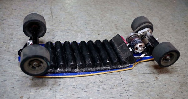
[Ben]’s pack is made up of A123 26650 cells nestled in his custom-fabricated enclosure. [Ben] designed his pack in CAD and used a CNC machine to create a foam mold. He used the mold to do a fiberglass layup, vacuum-bagged it, and left it to cure. Since the fiberglass bonded really well to the foam, [Ben] used acetone to dissolve the foam while leaving his fiberglass layup intact.

Bendy battery pack on longboard[Ben]’s pack fits 18 cells which he soldered together with some flexible copper grounding wire. The top side of the enclosure is covered with a layer of insulating rubber, and the rim is covered with a soft foam to form a gasket against the board. As you can see, the pack bends really well with the board, and  it doesn’t look like [Ben] has had any issues with his design so far. Check out [Ben]’s blog for more info and for more details on the overall design of his board.

A DIY Fourier Transform Spectrometer

Typical spectrometers use prisms or diffraction gratings to spread light over a viewing window or digital sensor as a function of frequency. While both prisms and gratings work very well, there are a couple of downsides to each. Diffraction gratings produce good results for a wide range of wavelengths, but a very small diffraction grating is needed to get high-resolution data. Smaller gratings let much less light through, which limits the size of the grating. Prisms have their own set of issues, such as a limited wavelength range. To get around these issues, [iliasam] built a Fourier transform spectrometer (translated), which operates on the principle of interference to capture high-resolution spectral data.

[iliasam]’s design is built with an assortment of parts including a camera lens, several mirrors, a micrometer, laser diode, and a bunch of mechanical odds and ends. The core of the design is a Michelson interferometer which splits and recombines the beam, forming an interference pattern. One mirror of the interferometer is movable, while the other is fixed. [iliasam]’s design uses a reference laser and photodiode as a baseline for his measurement, which also allows him to measure the position of the moving mirror. He has a second photodiode which measures the interference pattern of the actual sample that’s being tested.

Despite its name, the Fourier transform spectrometer doesn’t directly put out a FFT. Instead, the signal from both the reference and measurement photodiodes is passed into the sound card of a computer. [iliasam] wrote some software that processes the sampled data and, after quite a bit of math, spits out the spectrum. The software isn’t as simple as you might think – it has to measure the reference signal and calculate the velocity of the mirror’s oscillations, count the number of oscillations, frequency-correct the signal, and much more. After doing all this, his software calculates an interferogram, performs an inverse Fourier transform, and the spectrum is finally revealed. Check out [iliasam]’s writeup for all the theory and details behind his design.

Where 3000MPG+ Cars Come To Compete: The Ecomarathon

Every year teams from around the world come together for the Ecomarathon, an event (ironically put on by Shell) that tasks teams from high schools and universities with creating energy-efficient electric, gas, and hybrid vehicles. This year’s competition was held in Detroit, so I headed over to check it out.

vehicle-blur
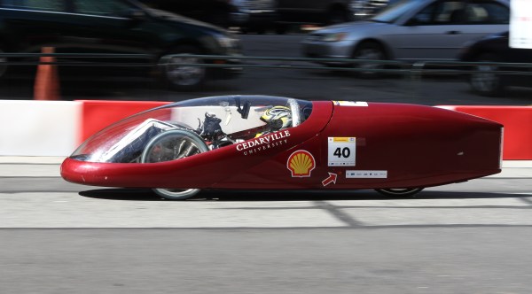
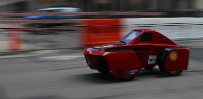
The event has two categories that vehicles compete in: prototype vehicles that compete for the highest fuel efficiency and “urban concept” vehicles that are more focused on normal driving environments and look slightly closer to street-legal vehicles. Cars in both categories can be fully electric or powered by gas, diesel, compressed natural gas, or other alternative fuels. Vehicles drive around a 0.9 mile track that weaves through downtown Detroit and the efficiency of each vehicle is measured as they complete a fixed number of laps around the track.

Continue reading “Where 3000MPG+ Cars Come To Compete: The Ecomarathon”

Modded Microwave Sets Its Own Clock

Of all the appliances in your house, perhaps the most annoying is a microwave with a flashing unset clock. Even though a lot of devices auto-set their time these days, most appliances need to have their time set after being unplugged or after a power outage. [Tiago] switches off power to some of his appliances while he’s at work to save a bit of power, and every time he plugs his microwave back in he has to manually reset the clock.

Thankfully [Tiago] wrote in with his solution to this problem: an add-on to his microwave that automatically sets the time over the network. [Tiago]’s project uses an ESP8266 running the Lua-based firmware we’ve featured before. The ESP module connects to [Tiago]’s WiFi network and pulls the current time off of his Linux server.

Next, [Tiago] ripped apart his microwave and tacked some wires on the “set time” button and on the two output pins of the microwave’s rotary encoder. He ran all three signals through optoisolators for safety, and then routed them to a few GPIO pins on his ESP module. When the microwave and the ESP module are powered up, [Tiago]’s Lua script pulls the time from his server, simulates a press of the “set time” button, and simulates the rotary encoder output to set the microwave’s time.

While [Tiago] didn’t post any detailed information on his build, it looks like a great idea that could easily be improved on (like adding NTP support). Check out the video after the break to see the setup in action.

Continue reading “Modded Microwave Sets Its Own Clock”

Reverse-Engineering A Wireless BBQ Thermometer

[Bob] has his own smoker and loves to barbecue, but doesn’t like spending all day checking on his smoker’s temperature. He thought about building his own wireless thermometer setup, which would have been pretty awesome, but then he had a better idea: why not hack an existing wireless barbecue thermometer? [Bob] purchased an off-the-shelf wireless BBQ thermometer and reverse-engineered its wireless protocol to make his own wireless thermometer setup.

The first problem [Bob] encountered was figuring out the frequency of the transmitter. Thankfully [Bob] had access to a spectrum analyzer, where he discovered the transmitter was running at 433.92MHz (a cheap RTL-SDR dongle would also get the job done). Next, [Bob] started digging into the manufacturer’s FCC filings and found that it actually called out the transmit frequency, which matched the transmit frequency he measured. He also found a ton of other helpful information in the filing, like a block diagram and full transmitter schematic.

[Bob] used a Radiometrix RF module to receive the thermometer’s signal. He hooked up the output to his logic analyzer to start decoding the protocol. After a quick visual analysis, [Bob] found that the signal was a preamble followed 13 bytes of Manchester-encoded data being transmitted at 2kbps. He started collecting data with known temperatures, created a table of the data, and began looking for patterns. After quite a bit of searching [Bob] was successfully able to find and parse the temperature values out of the data stream. [Bob] did a great job of documenting his process and results, so check out his writeup if you want to try it out yourself.

3D Spectrum Analyzer Uses 1280 LEDs

One of [Dooievriend]’s friends recently pressed him into service to write software for a 3d spectrum analyzer/VU that he made. The VU is a fairly complex build: it’s made up of 1280 LEDs in a 16x16x5 matrix controlled by a PIC32 clocked at 80MHz. [Dooievriend] wrote some firmware for the PIC that uses a variation on a discrete Fourier transform to create a 3D VU effect.

j6v2i 
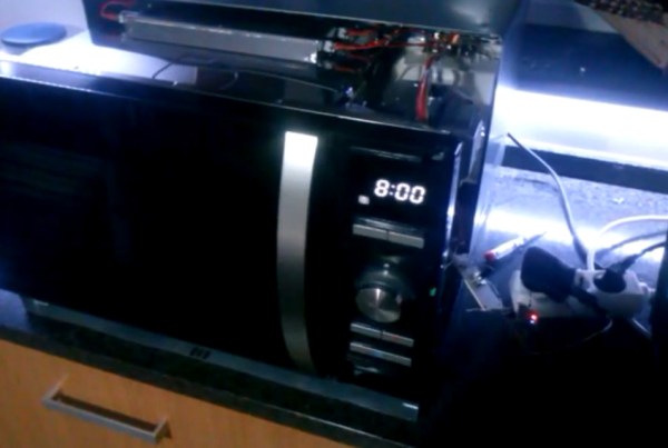
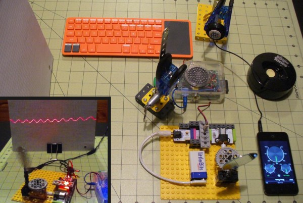
When [Dooievriend] set out to design the audio analyzing portion of the firmware, his mind jumped to the discrete Fourier transform. This transform calculates the amplitude in a series of frequency bins in the audio—seemingly perfect for a VU. However, after some more research, [Dooievriend] decided to implement a constant Q transform. This transform is very similar to a Fourier transform, but it takes into account the logarithmic way that the human ear interprets sound.

[Dooievriend] started implementing the constant Q transform using an interrupt-based sampler, but he quickly ran into issues with slow floating-point math on his PIC32 (which doesn’t have a hardware floating-point unit). Thankfully he rewrote his code using fixed-point math, and the transform runs nearly real-time. Check out the video after the break to see the VU in action, and a second video that gives some details on the hardware build.

Continue reading “3D Spectrum Analyzer Uses 1280 LEDs”

DIY Oscilloscope With A Scanning Laser

If you’ve ever used an old-school analog oscilloscope (an experience everyone should have!) you probably noticed that the trace is simply drawn by a beam that scans across the CRT at a constant rate, creating a straight line when there’s no signal. The input signal simply affects the y-component of the beam, deflecting it into the shape of your waveform. [Steve] wrote in to let us know about his home-built “oscilloscope” that works a lot like a simple analog oscilloscope, albeit with a laser instead of  a CRT.

[Steve]’s scope is built out of a hodgepodge of parts including Lego, an Erector set, LittleBits, and a Kano Computer (based on a Raspberry Pi). The Pi generates a PWM signal that controls the speed of a LittleBits motor. The motor is hooked up to a spinning mirror that sweeps the laser across some graph paper, creating a straight laser line.

After he got his sweep working, [Steve] took a small speaker and mounted a mirror to its cone. Next he mounted the speaker so the laser’s beam hits the mirror on the speaker, the spinning sweep mirror, and finally the graph paper display. The scope’s input signal (in this case, audio from a phone) is fed into the speaker which deflects the laser beam up and down as it is swept across the paper, forming a nice oscilloscope-like trace.

While [Steve]’s scope might not be incredibly usable in most cases, it’s still a great proof of concept and a good way to learn how old oscilloscopes work. Check out the video after the break to see the laser scope in action.

Continue reading “DIY Oscilloscope With A Scanning Laser”