Let’s face it — electronics are hard. Difficult concepts, tiny parts, inscrutable datasheets, and a hundred other factors make it easy to screw up in new and exciting ways. Sometimes the Magic Smoke is released, but more often things just don’t work even though they absolutely should, and no amount of banging your head on the bench seems to change things.
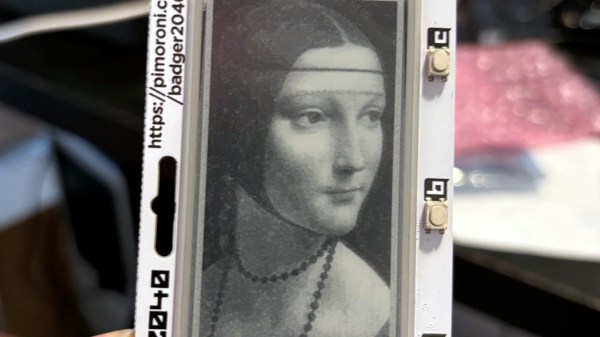
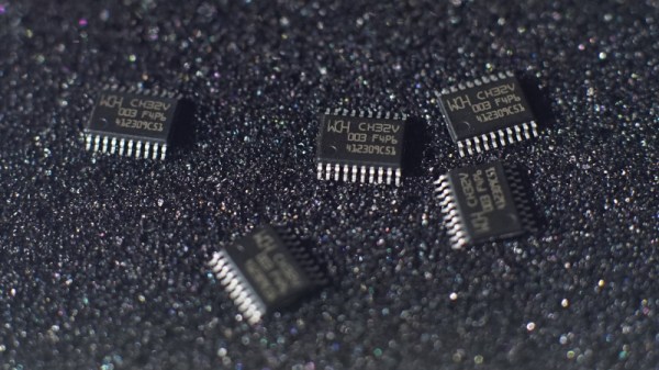
It’s at times like this that one questions their sanity, as [Gili Yankovitch] probably did when he discovered that not all CH32V003s are created equal. In an attempt to recreate the Linux-on-a-microcontroller project, [Gili] decided to go with the A4M6 variant of the dirt-cheap RISC-V microcontroller. This variant lives in a SOP16 package, which makes soldering a bit easier than either of the 20-pin versions, which come in either QFN or TSSOP packages.
Wisely checking the datasheet before proceeding, [Gili] was surprised and alarmed that the clock line for the SPI interface didn’t appear to be bonded out to a pin. Not believing his eyes, he turned to the ultimate source of truth and knowledge, where pretty much everyone came to the same conclusion: the vendor done screwed up.
Now, is this a bug, or is this a feature? Opinions will vary, of course. We assume that the company will claim it’s intentional to provide only two of the three pins needed to support a critical interface, while every end user who gets tripped up by this will certainly consider it a mistake. But forewarned is forearmed, as they say, and hats off to [Gili] for taking one for the team and letting the community know.