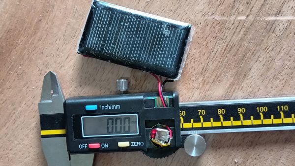
[Gio] enjoys using vacuum tubes in his projects. He designs the circuits using a CAD program but was finding that there is no substitute for actually building a prototype before heading to a final design. To make this process easier, he built his own tube prototyping station.
At the top of the board he’s got three different sizes of tube sockets with the pins from each wired as common. The nine pins from the sockets break out to a terminal strip where they can be interfaced with a solderless breadboard. For added versatility he’s included terminals to tap into some RCA jacks, as well as a 100 kOhm variable resistor. We’d bet this is not something that you can find ready-made, but it sure does look a whole lot better than a workbench full of components alligator-clipped together.
[Johndavid400] built this incredible looking R/C lawnmower. After spending some time repairing broken R/C cars, he wanted to move on to something a little more useful and powerful. He decided to build a mower. He’s using a transceiver set from ebay, with an Arduino interpreting the signal and outputting to his custom motor board. In the video after the break, you can see that the mower looks responsive and quick. He does note, however, that he had some glitches early in the process that left him with a runaway mower. We covered a very similar mower ages ago that used a wheelchair as the base.
[Kizo] repurposed a flatbed scanner to use as an exposure box for making printed circuit boards. Exposure time is controlled by an AVR ATtiny2313 microcontroller. The device is connected to a separate display board to control four 7-segment displays using one shift register for each. Time is set in ten second increments and once started, switches on the lights with a relay. Once the right exposure time has been reached, the lights are switched off and a piezo speaker is buzzed. There’s no mention of they type of bulbs he’s using but they look like compact fluorescent with tin foil beneath as a reflector.
We’ve covered homebrew PCBfabricationtechniques about a billiontimesbefore. What sets this tutorial apart is that it collects many bits of knowledge otherwise scattered all about the web, and then depicts the entire process on video, from initial printing to cut PCB…because reading about it versus seeing it done are two different things entirely. They give a number of immensely useful tips throughout: choice of materials and where to get them, tools and techniques, and dispelling several myths about these methods (for example, they’re adamant about notusing acetone to clean toner from the PCB). Well worth the 30 minutes to watch. If that’s too much and you’ve been stuck on just one part of the process, the tutorial is in three segments.
Trimming finished boards on a paper cutter? Who would’ve guessed?
Starting a new robotics project and want to find the perfect servo for the job? It can be a real pain in butt sometimes. This is where ServoDatabase.com comes in. They’re compiling specifications and reviews on servos. We love seeing these databases pop up. Remember the online chip reference? You simply can not have too much reference material.
Xerox has announced a breakthrough in printable circuits. They’ve developed a conductive ink called “silver bullet” that can be printed on many different types of substrate to create circuits. The key part of the new ink is its lower melting point. Plastic film substrate melts at 150 degrees Celsius but the ink is liquid when ten degrees cooler to avoid damaging the film. This begs the question: how do you then solder components to the circuit?
The benefits of printable circuitry are obvious. Aside from cheaper and easier RFID, disposable circuits like greeting cards, and fabric-based electronics, we’re hoping this will facilitate more environmentally friendly PCB fabrication. That really depends on the ink’s production process and the resilience of the resulting circuitry.
Above is a video detailing one method for populating a two sided surface mount PCB. We covered using a stencil to apply solder paste for a PCB a few weeks ago. In the comments there was a debate about the virtue of using stencils as well as a question about how two sided boards are populated. This was a good question because reflowing a board twice can cause components on the underside to fall off.
[Wim L's] comment mentions that there are a couple of methods for two sided population. In the video you will see that a stencil is not being used, but instead, paste is applied by a pedal actuated syringe. The paste is applied to the underside of the board first, then a teeny dot of epoxy is added to hold the component in place. Each part is then positioned normally and baked in a reflow oven. This process both reflows the solder, and cures the epoxy. When the board is reflowed a second time, the epoxy holds the bottom components in place as the top solder reaches its melting point.
This method of applying solder paste is slower than using a stencil. But if done correctly, every component can get the amount of solder needed.
Here’s a project from back in 2001 that might be of interest to some of you. It is a guide on how to build your own hot air pencil for SMD soldering. He is using a super cheap 45W soldering iron from “the shack” combined with a pump type desoldering tool and an aquarium pump. He says it works pretty well, and we don’t see why it shouldn’t. This is a pretty elegant solution. There are also some more recent versions of this mod, but the idea is basically the same.
A dedicated rolling chest for one’s tools is among the most indulgent yet worthwhile acquisitions. Having everything mobile and organized for quick access improves efficiency and keeps the shop tidy. But holy living crap, have you priced these things? Even a mediocre setup costs more than the gross national product of some small nations!
Here’s a project that tarts up a dresser into a passable tool chest. Using casters, modern drawer pulls and a tidy paint job, they turn a nasty old dresser into something presentable. It’s nowhere near as slick as the commercial units…no ball bearing glides, not chemical resistant, and your macho grease monkey friends will just roll their eyes…but if you’d rather spend your hard-earned money on more and bettertools than a pretty box to put them in, this might be just the thing. From across the room, you’d hardly know the difference.
A good tool chest will include several shallow drawers so that all the tools are visible at a glance and not buried in a jumble. If searching for a piece of furniture to re-use, look for something with multiple slim drawers rather than just a few deep ones; a large jewelry chest might work well.
[Oleg] is the creator of the USB Isolator and therefore has a need to frequently populate the same board. He’s using an acrylic frame that fits the PCB perfectly to hold it in place so that paste and be applied right up to the edges of the board. He ordered a laser cut Kapton stencil for applying the solder. The paste is squeegeed into the stencil holes, the stencil is removed, and parts are placed with tweezers and a steady hand. For the final step, the boards go into an old toaster oven for reflow.
[Oleg] uses temperature marker on his boards to monitor the progress of the reflow. This marker is basically a crayon that begins to melt at a specific temperature. When the board has cooled, the melted mark can be scraped away or removed with alcohol.
Of course this is only really useful if you have a bunch of high-quality boards to populate. But with the relatively low cost of getting professionally made boards we think the need for this type of assembly process is on the rise.