Waveform Generator Teardown Is Nearly Empty

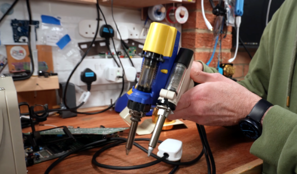
We always enjoy [Kerry Wong]’s insightful teardowns, and recently, he opened up a UTG1042X arbitrary waveform generator. Getting inside was a bit of a challenge since there were no visible screws. Turns out, they were under some stickers. We always dislike that because it is very difficult to get the unit to go back together.

Once open, the case reveals it is almost completely empty. The back panel has a power supply, and the front panel has all the working circuitry. The box seems to be for holding the foot and preventing the device from getting lost on your bench.

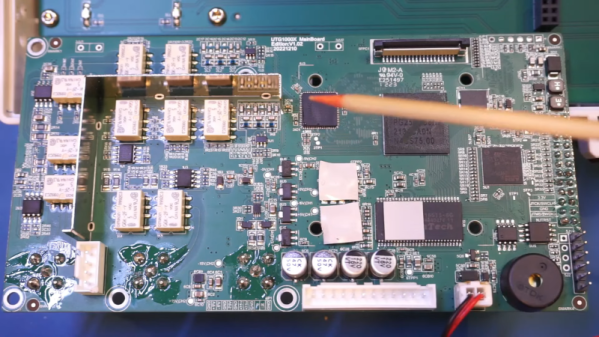
The power supply is unremarkable. There are a few odd output voltages. The main board is a bit more interesting, especially after removing the heat sink. There are two channels, but the board isn’t laid out, with a lot of segregation between the two channels. That makes sense with the output sections clustered together and the digital section with the CPU, FPGA, and the DAC in close proximity.

The other side of the board connects to a very simple display board. It would be interesting to compare this to a circa-1980s AWG, which would have been far more complicated.

Making a waveform generator with a microprocessor and a DAC isn’t hard. The hard part is the output stages and maximizing the operating speed.

Continue reading “Waveform Generator Teardown Is Nearly Empty”

No Lathe? Build Your Own

If you need to make round things, you probably need a lathe. Can you build one as nice as one you can buy? Probably not. But can you build one that will work and allow you to do more things than having no lathe at all? [Mikeandmertle] say absolutely! You can see the contraption in operation in the video below.

The build is decidedly functional-looking and only requires a few parts. Most of the components are unremarkable, save for a threaded bar, a metal pipe, some bearings, and a few threaded inserts. Well, there’s also a drill chuck and two lathe centers. Those don’t have to be very expensive, but they may well be the bulk of what you have to spend to make this project.

Continue reading “No Lathe? Build Your Own”

Let Your Finger Do The Soldering With Solder Sustainer V2

Soldering is easy, as long as you have one hand to hold the iron, one to hold the solder, and another to hold the workpiece. For those of us not so equipped, there’s the new and improved Solder Sustainer v2, which aims to free up one of however many hands you happen to have.

Eagle-eyed readers will probably recall an earlier version of Solder Sustainer, which made an appearance in last year’s Hackaday Prize in the “Gearing Up” round. At the time we wrote that it looked a bit like “the love child of a MIG welder and a tattoo machine.” This time around, [RoboticWorx] has rethought that concept and mounted the solder feeder on the back of a fingerless glove. The solder guide is a tube that clips to the user’s forefinger, which makes much finer control of where the solder meets the iron possible than with the previous version. The soldering iron itself is also no longer built into the tool, giving better control of the tip and letting you use your favorite iron, which itself is no small benefit.

Hats off to [RoboticWorx] for going back to the drawing board on this one. It isn’t easy to throw out most of your design and start over, but sometimes it just makes sense.

Continue reading “Let Your Finger Do The Soldering With Solder Sustainer V2”

Adjustable Lights Help Peer Inside Chips With IR

If you’re used to working through a microscope, you’ve probably noticed that the angle of the light greatly affects how your workpiece looks. Most of us prefer the relatively flat lighting provided by a ring light, but variable angle side lighting can be useful too, especially when you’re peering inside ICs to make sure the silicon is what it’s supposed to be.

That’s what [Bunnie] is working on these days with his Project IRIS, short for “Infrared in situ,” a non-destructive method for looking inside chip packages. The technique relies on the fact that silicon is transparent to certain wavelengths of light, and that some modern IC packages expose the underside of the silicon die directly to the outside world. Initial tests indicated that the angle of the incident IR light was important to visualizing features on the metal interconnects layered onto the silicon, so [Bunnie] designed a two-axis light source for his microscope. The rig uses curved metal tracks to guide a pair of IR light sources through an arc centered on the focal point of the microscope stage. The angle of each light source relative to the stage can be controlled independently, while the whole thing can swivel around the optical axis of the microscope to control the radial angle of the lighting.

The mechanism [Bunnie] designed to accomplish all this is pretty complex. Zenith angle is controlled by a lead screw driving a connecting rod to the lights on their guide tracks, while the azimuth of the lights is controlled by a separate motor and pulley driving a custom-built coaxial bearing. The whole optical assembly is mounted on a Jubilee motion platform for XYZ control. The brief videos below show the lights being put through their paces, along with how changing the angle of the light affects the view inside a chip.

Continue reading “Adjustable Lights Help Peer Inside Chips With IR”

Squishy Miter Saw Shroud Spares You The Sneezy Bits

Let’s be honest. When it comes to operating miter saws, these tools kick dust out the back like a spray paint can. Most of us have accepted this quirk as-is, but not [Inspire Woodcraft] who’s on a mission to achieve near perfect dust collection. And he nearly has it. With a budget dust collection setup, he’s able to eliminate over 90% of the dust from his cuts, and others who’ve adopted his setup can vouch for his results.

The solution comes in two pieces. First, he focuses on creating a new dust shroud or “boot” for collecting dust through the vacuum hookup on the back of the saw. What’s key here is that this dust boot is made from squishy silicone, enabling it to flare outwards and spread out as the saw travels downward into the material. It’s clear that [Inspire Woodcraft] has gone through dozens of material and shape iterations, but the result is sturdy enough to stay open with the vacuum running through the back hose attachment.

With the dust nearly perfectly funneled from the back, the second tweak focuses on rerouting stray dust away from the table and directly into this boot. [Inspire Woodcraft] later noticed that dust collection from the bottom of his miter saw simply didn’t exist, so dust would accumulate at his feet.

His solution? To create a second shroud that fits under the throat plate that takes sawdust once destined for the ground and ejects it backwards and straight into the dust collection boot.

Altogether, this setup solves a long-existing problem with a handful of commodity parts and a few 3D prints. [Inspire Woodcraft] has also chronicled his journey in such detail where you too could recreate his solution from the video. But if you’re feeling lazy, and you’re lucky enough to own the same Dewalt DW716 or DWS716 model miter saws, you can simply snag a kit from his website.

If all this talk of miter saws has your reaching for a screwdriver to see what modified mayhem you can unleash with yours, look no further than this LED hack that adds a shadow line to your cuts.

Continue reading “Squishy Miter Saw Shroud Spares You The Sneezy Bits”

Comparing Desoldering Tools

[Lee] has a Hakko FR301 desoldering gun and a Duratool knockoff. He freely admits that the Hakko is probably better, but he wonders if it’s good enough to justify being four times as expensive. He shows both of them off in a recent video that you can see below.

Often, desoldering doesn’t get as much attention as soldering, but for repairs or if you make mistakes —  and who doesn’t — it is an essential skill. Many of the differences will be either good or bad, depending on your personal preference. For example, the Hakko is an all-in-one unit, so it doesn’t have a bulky box to sit on your bench. However, that also means the Hakko is larger and heavier. It also lacks controls and indicators the other unit has on the base station box.

Continue reading “Comparing Desoldering Tools”

The line injector shown characterising the PSRR of an AMS1117 regulator, with a bunch of stuff connected to it through SMA jacks

A Simple Line Injector Shows You The Wonderful World Of PSRR

[limpkin] writes us to show a line injector they’ve designed. The principle is simple — if you want to measure how much PSU noise any of your electronic devices let through, known as PSRR (Power Supply Rejection Ratio), you can induce PSU noise with this board, and then measure noise on your device’s output. The board is likewise simple. A few connectors, resistors, and caps, and a single N-FET!

You do need a VNA, but once you have that, you get a chance to peek into an entire world of insights. Does that 1117 LDO actually filter out noise better than a buck regulator? Is it enough to use a Pi filter for that STM32’s ADC rail, and do the actual parts you’re using actually help with that task? How much noise does your device actually let through in the real world, after being assembled with the specific components you’ve picked? [limpkin] shows us a whole bunch of examples – putting regulators, filters and amplifiers to the test, and showing us how there’s more than meets the eye.

Everything is open source, with full files available on the blog. And, if you want it pre-assembled, tested and equipped with the CNC-milled case, you can get it on Tindie or Lektronz! Of course, even without a tool like this, you can still get good filter designs done with help of computer-aided modelling.

We thank [alfonso] for sharing this with us!