Low-power radios, often referred to in the amateur radio community as QRP radios, have experienced a resurgence in popularity lately. Blame it on certain parts of the hobby become more popular, like Parks on the Air (POTA) or Summits on the Air (SOTA). These are events where a radio operator operates off-grid at remote parks or mountaintops. These QRP rigs are a practical and portable way to make contacts. You would think that a five- or ten-watt rig running on batteries would be simple. Surprisingly, they can be enormously complex and expensive. That’s why [Dr. Daniel Marks] built the RFBitBanger, a QRP radio designed to not only be usable off-grid but to be built and maintained off-grid as well.
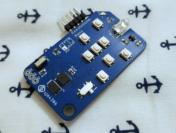
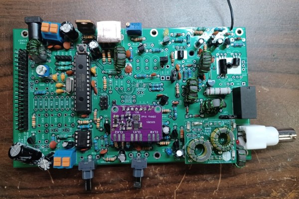
The radio accomplishes this goal by being built out of as many standard off-the-shelf components as possible. It eschews modern surface-mount components in favor of the much more accessible through-hole parts, including the ATMEGA328P at the center of the build. A PCB design is also available, but it can be built on perf board nearly as easily. The radio supports any mode a QRP operator might use, including CW, SSB, RTTY, and a new mode designed explicitly for this radio called SCAMP which is a low bandwidth, low SNR digital mode built into the Arduino-based firmware. It’s a single-band radio, but any band between 20 and 80 meters can be selected with pluggable filters.
As far as bomb-proof radios go, we can’t imagine a better way to live out an apocalypse than with a radio like this. As long as there’s a well-stocked parts drawer around, this radio could theoretically reach around the world without worrying about warranty claims, expensive parts, or even a company going out of business or not stocking parts for old radios anymore. There’s also more information about this build at the Open Research Institute for those interested. And, if you’re wondering how useful any radio could be using only five watts of transmitter power, take a look at this in-depth look at QRP radio operation.
Thanks to [Stephen Walters] for the tip.