An Electromagnet Brings Harmony To This Waving Cat

We’ve noticed waving cats in restaurants and stores for years, but even the happy bobbing of their arm didn’t really catch our attention. Maybe [Josh] had seen a couple more than we have when it occurred to him to take one apart to see how they work. They are designed to run indoors from unreliable light sources and seem to bob along forever. How do the ubiquitous maneki-neko get endless mechanical motion from one tiny solar cell?

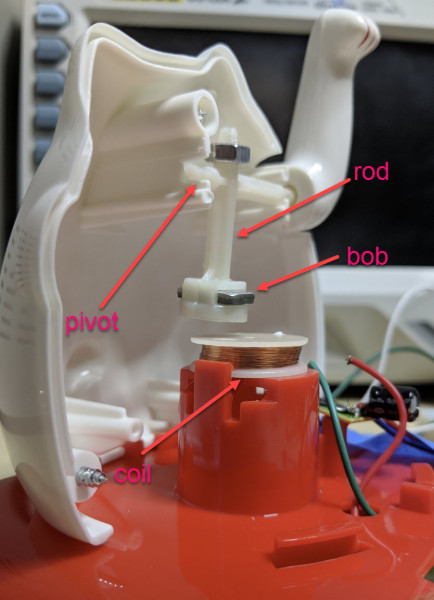
Perhaps unsurprisingly given the prevalence and cost of these devices, the answer is quite simple. The key interaction is between a permanent magnet mounted to the end of the waving arm/pendulum and a many-turn wire coil attached to the body. As the magnet swings over the coil, its movement induces a voltage. A small blob of analog circuitry reacts by running current through the coil. The end effect is that it “senses” the magnet passing by and gives it a little push to keep things moving. As long as there is light the circuit can keep pushing and the pendulum swings forever. If it happens to stop a jolt from the coil starts the pendulum swinging and the rest of the circuit takes over again. [Josh] points to a similar circuit with a very nice write up in an issue of Nuts and Volts for more detail.

We’ve covered [Josh]’s toy teardowns before and always find this category of device particularly interesting. Toys and gadgets like the maneki-neko are often governed by razor-thin profit margins and as such must satisfy an extremely challenging intersection of product constraints, combining simple design and fabrication with just enough reliability to not be a complete disappointment.

For more, watch [Josh] describe his method in person after the break, or try flashing his code to an Arduino and make a waving cat of your own.

Continue reading “An Electromagnet Brings Harmony To This Waving Cat”

Cloverleaf Satellite Antenna Mounted on a Pole

Tracking CubeSats For $25

CubeSats are tiny satellites which tag along as secondary payloads during launches. They have to weigh in at under 1.33 kg, and are often built at low cost. There’s even open source designs for these little spacecrafts. Over 800 CubeSats have been launched over the last few years, with many more launches scheduled in the near future.

[Thomas Cholakov] coupled a homemade cloverleaf antenna to a software-defined radio to track some of these satellites. The antenna is built out of copper-clad wire cut to the correct length to receive 437 MHz signals. Four loops are connected together and terminated to an RF connector.

This homebrew antenna is connected into a RTL-SDR dongle. The dongle picks up the beacon signals sent by the satellites and provides the data to a PC. Due to the motion of the satellites, their beacons can be easily identified by the Doppler shift of the frequency.

[Thomas] uses SDR Console to receive data from the satellites. While the demo only shows basic receiving, much more information on decoding these satellites can be found on the SDR Satellites website.

This looks like a fun weekend project, and probably the cheapest aerospace related project possible. After the break, watch the full video explaining how to build and set up the antenna and dongle.

Continue reading “Tracking CubeSats For $25”

How Cheap Can A 3D Printer Get? The Anet A8

The short answer: something like $200, if your time is worth $0/hour. How is this possible? Cheap kit printers, with laser-cut acrylic frames, but otherwise reasonably solid components. In particular, for this review, an Anet A8. If you’re willing to add a little sweat equity and fix up some of the bugs, an A8 can be turned into a good 3D printer on a shoestring budget.

That said, the A8 is a printer kit, not a printer. You’re going to be responsible for assembly of every last M3 screw, and there are many. Building the thing took me eight or ten hours over three evenings. It’s not rocket surgery, though. There are very accessible videos available online, and a community of people dedicated to turning this box of parts into a great machine. You can do it if you want to.

This article is half how-to guide and half review, and while the fun of a how-to is in the details, the review part is easy enough to sum up: if you want the experience of building a 3D printer, and don’t mind tweaking to get things just right, you should absolutely look into the A8. If you want a backup printer that can print well enough right after assembly, the A8 is a good deal as well; most of the work I’ve put into mine is in chasing perfection. But there are a couple reasons that I’d hesitate to recommend it to a rank beginner, and one of them is fire.

Still, I’ve put 1,615 m (1.0035 miles) of filament through my A8 over 330 hours of run-time spread across the last three months — it’s been actively running for 15% of its lifetime! Some parts have broken, and some have “needed” improving, but basically, it’s been a very functional machine with only three or four hours of unintentional downtime. My expectations going in were naturally fairly low, but the A8 has turned out to be not just a workhorse but also a decent performer, with a little TLC. In short, it’s a hacker’s printer, and I love it.

Continue reading “How Cheap Can A 3D Printer Get? The Anet A8”

Worried About Running Out Of Filament Mid-Print? Join It!

If you’ve ever cringed over throwing away any printer filament you know wouldn’t cover your next small part — let alone an overnight print — you may appreciate [starlino]’s method for joining two spools of filament together.

While there are other methods to track how much filament you’re using, this method removes some of the guesswork. First, snip the ends of the filament on a diagonal — as close to the same angle as possible. Cover both ends with shrink wrap tubing — 2mm tubing for 1.75mm filament for example — ensuring that the two ends overlap inside the wrap. Tape the filament to a heat resistant mat with Kapton tape, leaving exposed the joint between the two filaments. A temperature sensor may help you to find your filament’s melting point, or you can experiment as necessary to get a feel for it.

Melt the filament inside the tubing with a hot air soldering station or heat gun and cool it down promptly with a few blasts from an air duster. All that’s left is to cut the filament free of the tape and shrink wrap, scraping away any excess so as to prevent printer jams. Done! Now, back to printing! Check out the tutorial video after the break.nning

Continue reading “Worried About Running Out Of Filament Mid-Print? Join It!”

The Evolution Of A DIY Circuit Board Plotter

In this three part video series we watch [Dirk Herrendoerfer] go from scraps to a nice 3D printed assembly as he iterates through the design of a pen plotter for making circuit boards.

[dana] mentioned [Dirk]’s work in the comments of this post which describes a different process. Many permanent markers stick to copper well enough to last through the chemical etching process. While hand drawing definitely produces some cool, organic-looking boards, for sharp lines and SMDs it gets a bit harder; to the point where it becomes advisable to just let a robot do it.

Of course, [Dirk] was aware of this fact of life. He just didn’t have a robot on hand. He did have some electronic detritus, fishing line, an Arduino, scrap wood, brass tubes, and determination.  The first version‘s frame consisted of wooden blocks set on their ends with holes drilled to accept brass rods. The carriage was protoboard and hot glue. Slightly larger brass tubing served as bushings and guide. As primitive as it was the plotter performed admirably, albeit slowly.

The second version was a mechanical improvement over the first, but largely the same. The software got a nice improvement. It worked better and had some speed to it.

The latest version has some fancy software upgrades; such as acceleration. The frame has gone from random bits of shop trash to a nicely refined 3D printed assembly. Even the steppers have been changed to the popular 28BYJ-48 series. All the files, software and hardware, are available on GitHub. The three videos are viewable after the break. It’s a great example of what a good hacker can put together for practically no money.

Continue reading “The Evolution Of A DIY Circuit Board Plotter”

Multipurpose Robot For The Masses

As the cost of almost every technology comes falling down, from electronics to batteries to even tools like 3D printers, the cost to build things formerly out of reach of most of us becomes suddenly very affordable. At least, that’s what [John Choi] has found by building a completely DIY general purpose robot for around $2000.

OK, so $2000 isn’t exactly “cheap” but considering that something comparable (like Baxter) costs north of what a new car would cost means that [John] has dropped the price for a general-purpose robot by an order of magnitude. And this robot doesn’t skimp on features, either. It has a platform that allows it to navigate rooms, two manipulating limbs with plenty of servos, a laptop “head” that allows for easy interface, testing, and programming, and an Arduino Mega that allows it to interface with any sensors or other hardware with ease. It’s also modular so it can be repaired and transported easily, and it uses open source software and open hardware so it’s easy to build on.

This robot is an impressive piece of work that should help bring this technology to more than just high-end factories and research labs. They’ve already demonstrated the robot watering plants, playing the piano, picking things up, and many other tasks. We’d say that they’re well on their way to their goal of increasing the number of students and hobbyists who have access to this technology. If the $2k price tag is still too steep, though, there are other ways of getting into robotics without diving headfirst into a Baxter-like robot.

Continue reading “Multipurpose Robot For The Masses”

The Sincerest Form Of Flattery: Cloning Open-Source Hardware

We’re great proponents (and beneficiaries) of open-source hardware here at Hackaday. It’s impossible to overstate the impact that the free sharing of ideas has had on the hacker hardware scene. Plus, if you folks didn’t write up the cool projects that you’re making, we wouldn’t have nearly as much to write about.

We also love doing it ourselves. Whether this means actually etching the PCB or just designing it ourselves and sending it off to the fab, we’re not the types to pick up our electronics at the Buy More (except when we’re planning to tear them apart). And when we don’t DIY, we like our electrons artisanal because we like to support the little guy or girl out there doing cool design work.

So it’s with a moderately heavy heart that we’ll admit that when it comes to pre-built microcontroller and sensor boards, I buy a lot of cheap clones. Some of this is price sensitivity, to be sure. If I’m making many different one-off goofy projects, it just doesn’t make sense to pay the original-manufacturer premium over and over again for each one. A $2 microcontroller board just begs to be permanently incorporated into give-away projects in a way that a $20 board doesn’t. But I’m also positively impressed by some of the innovation coming out of some of the clone firms, to the point that I’m not sure that the “clone” moniker is fair any more.

This article is an attempt to come to grips with innovation, open source hardware, and the clones. I’m going to look at these issues from three different perspectives: the firm producing the hardware, the hacker hobbyist purchasing the hardware, and the innovative hobbyist who just wants to get a cool project out to as many people as possible. They say that imitation is the sincerest form of flattery, but can cloning go too far? To some extent, it depends on where you’re sitting.

Continue reading “The Sincerest Form Of Flattery: Cloning Open-Source Hardware”