MIT’s Hair-Brushing Robot Untangles Difficult Robotics Problem

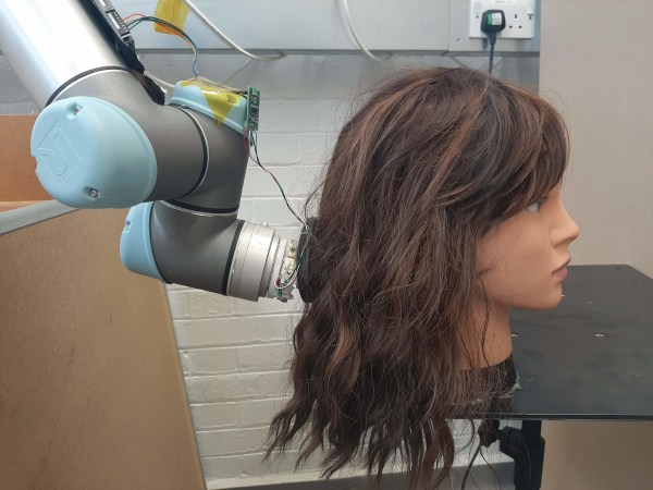
Whether you care to admit it or not, hair is important to self-image, and not being able to deal with it yourself feels like a real loss of independence. To help people with limited mobility, researchers at MIT CSAIL have created a hair-brushing robot that combines a camera with force feedback and closed-loop control to adjust to any hair type from straight to curly on the fly. They achieved this by examining hair as double helices of soft fibers and developed a mathematical model to untangle them much like a human would — by working from the bottom up.

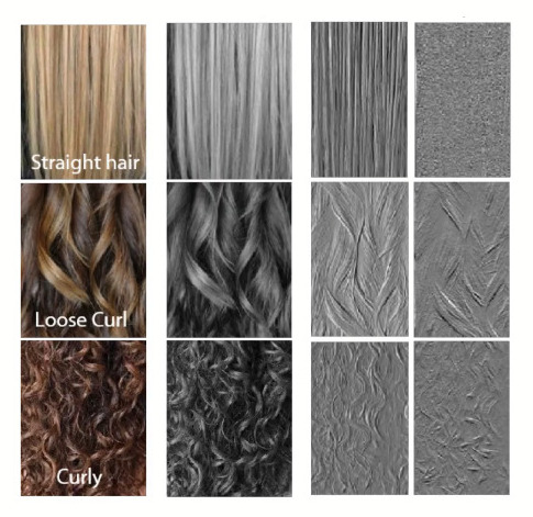
It may look like a hairbrush strapped to a robot arm, but there’s more to it than that. Before it ever starts brushing, the robot’s camera takes a picture that gets cropped down to a rectangle of pure hair data. This image is converted to grayscale, and then the program analyzes the x/y image gradients. The straighter the hair, the more edges it has in the x-direction, whereas curly hair is more evenly distributed. Finally, the program computes the ratio of straightness to curliness, and uses this number to set the pain threshold.

The brush is equipped with sensors that measure the forces being exerted on the hair and scalp as it’s being brushed, and compares this input to a baseline established by a human who used it to brush their own hair. We think it would be awesome if the robot could grasp the section of hair first so the person can’t feel the pull against their scalp, and start by brushing out the ends before brushing from the scalp down, but we admit that would be asking a lot. Maybe they could get it to respond to exclamations like ‘ow’ and ‘ouch’. Human trials are still in the works. For now, watch it gently brush out various wigs after the break.

Even though we have wavy hair that tangles quite easily, we would probably let this robot brush our hair. But this haircut robot? We’re not that brave.

Continue reading “MIT’s Hair-Brushing Robot Untangles Difficult Robotics Problem”

Flexible Actuators Spring Into Action

Most experiments in flexible robot actuators are based around pneumatics, but [Ayato Kanada] and [Tomoaki Mashimo] has been working on using a coiled spring as the moving component of a linear actuator. Named the flexible ultrasonic motor (FUSM), [Yunosuke Sato] built on top of their work and assembled a pair of FUSM into a closed-loop actuator with motion control in two dimensions.

A single FUSM is pretty interesting by itself, its coiled spring is the only mechanical moving part. An earlier paper published by [Kanada] and [Mashimo] laid out how to push the spring through a hole in a metal block acting as the stator of this motor. Piezoelectric devices attached to that block minutely distorts it in a controlled manner resulting in linear motion of the spring.

For closed-loop feedback, electrical resistance from the free end of the spring to the stator block can be measured and converted to linear distance to within a few millimeters. However, the acting end of the spring might be deformed via stretching or bending, which made calculating its actual position difficult. Accounting for such deformation is a future topic for this group of researchers.

This work was presented at IROS2020 which like many other conferences this year, moved online and became IROS On-Demand. After a no-cost online registration we can watch the 12-minute recorded presentation on this project or any other at the conference. The video includes gems such as an exaggerated animation of stator block deformation to illustrate how a FUSM works, and an example of the position calculation challenge where the intended circular motion actually resulted in an oval.

Speaking of conferences that have moved online, we have our own Hackaday Remoticon coming up soon!

Continue reading “Flexible Actuators Spring Into Action”

Open-Source Arm Puts Robotics Within Reach

In November 2017, we showed you [Chris Annin]’s open-source 6-DOF robot arm. Since then he’s been improving the arm and making it more accessible for anyone who doesn’t get to play with industrial robots all day at work. The biggest improvement is that AR2 had a closed-loop control system, and AR3 is open-loop. If something bumps the arm or it crashes, the bot will recover its previous position automatically. It also auto-calibrates itself using limit switches.

AR3 is designed to be milled from aluminium or entirely 3D printed. The motors and encoders are controlled with a Teensy 3.5, while an Arduino Mega handles I/O, the grippers, and the servos. In the demo video after the break, [Chris] shows off AR3’s impressive control after a brief robotic ballet in which two AR3s move in hypnotizing unison.

[Chris] set up a site with the code, his control software, and all the STL files. He also has tutorial videos for programming and calibrating, and wrote an extremely detailed assembly manual. Between the site and the community already in place from AR2, anyone with enough time, money and determination could probably build one. Check out [Chris]’ playlist of AR2 builds — people are using them for photography, welding, and serving ice cream. Did you build an AR2? The good news is that AR3 is completely backward-compatible.

The AR3’s grippers work well, as you’ll see in the video. If you need a softer touch, try emulating an octopus tentacle.

Continue reading “Open-Source Arm Puts Robotics Within Reach”

Derek Schulte: Path Planning For 3D Printers

[Derek Schulte] designed and sells a consumer 3D printer, and that gives him a lot of insight into what makes them tick. His printer, the New Matter MOD-t, is different from the 3D printer that you’re using now in a few different ways. Most interestingly, it uses closed-loop feedback and DC motors instead of steppers, and it uses a fairly beefy 32-bit ARM processor instead of the glorified Arduino Uno that’s running many printers out there.

The first of these choices meant that [Derek] had to write his own motor control and path planning software, and the second means that he has the processing to back it up. In his talk, he goes into real detail about how they ended up with the path planning system they did, and exactly how it works. If you’ve ever thought hard about how a physical printhead, with momentum, makes the infinitely sharp corners that it’s being told to in the G-code, this talk is for you. (Spoiler: it doesn’t break the laws of physics, and navigating through the curve involves math.)

Continue reading “Derek Schulte: Path Planning For 3D Printers”

3-Phase BLDC Motor Controller Will Run You $20 In Parts

If you’re an active shopper on RC websites, you’ll find tiny motors spec’ed at hundreds of watts while weighing just a few grams, like this one. Sadly, their complementary motor controllers are designed to drive them at a high speed, which means we can only hit that “520-watt” power spec by operating in a max-speed-minimum-torque configuration. Sure, that configuration is just fine for rc plane and multicopter enthusiasts, but for roboticists looking to drive these bldc motors in a low-speed-high-torque configuration, the searches come up blank.

The days in the dust are coming to an end though! [Cameron] has been hard at work at a low cost, closed-loop controller for the robotics community that will take a conventional BLDC airplane motor and transform it into a high end servo motor. Best of all, the entire package will only run you about $20 in parts–including the position sensor!

“Another BLDC motor controller?” you might think. “Surely, I’ve seen this before“. Fear not, faithful readers; [Cameron’s] solution will get even the grumpiest of engineers to crack a smile. For starters, he’s closing the loop with a Melexis MLX90363 hall effect sensor to locate the rotor position. Simply glue a small magnet to the shaft, calibrate the magnetic field with one revolution, and–poof–a wild 14-bit encoder has appeared! Best of all, this solution costs a mere $5 to $10 in parts.

Next off, [Cameron] uncovered a little-known secret of the ATMEGA32u4, better known as the chip inside the Arduino Leonardo. It turns out that this chip’s TIMER4 peripheral contains a feature designed exclusively for 3-phase brushless motor control. Complementary PWM outputs are built into 3 pairs of pins with configurable dead time built into the chip hardware. Finally, [Cameron] is pulsing the FETs at a clean 32-Khz — well beyond the audible range, which means we won’t hear that piercing 8-Khz whine that’s so characteristic of cheap BLDC motor controllers.

Curious? Check out [Cameron’s] firmware and driver design on the Githubs.

Of course, there are caveats. [Cameron’s] magnetic encoder solution has a few milliseconds of lag that needs to be characterized. We also need to glue a magnet to the shaft of our motor, which won’t fly in all of our projects that have major space constraints. Finally, there’s just plain old physics. In the real world, motor torque is directly proportional to current, so stalling an off-the-shelf bldc motor at max torque will burn them out since no propeller is pushing air through them to cool them off. Nevertheless, [Cameron’s] closed loop controller, at long last, can give the homebrew robotics community the chance to explore these limits.

Is It A Stepper? Or Is It A Servo?

Almost everyone who is involved with 3D printing thinks to themselves at some point, “this could all be done using a closed-loop system and DC motors”. Or at least everyone we know. There’s even one commercial printer out there that uses servo control, but because of this it’s not compatible with the rest of the (stepper-motor driven) DIY ecosystem.

[LoboCNC] wanted to change this, and he’s in a unique position to do so, having previously built up a business selling PIC-based servo controllers. His “servololu” is essentially a microcontroller and DC motor driver, with an input for a quadrature encoder for feedback. The micro takes standard step/direction input like you would use to drive a stepper motor, and then servos the attached DC motor to the right position. It even signals when it has an error.
Continue reading “Is It A Stepper? Or Is It A Servo?”

Closed Loop Control For 3D Printers

One of the bigger problems with any CNC machine or 3D printer is the issue of missed steps when moving the toolhead. If a stepper motor misses a step, the entire layer of the print – and every layer thereafter – will be off by just a tiny bit. Miss a few more steps, and that print will eventually make its way into the garbage. [Misan] has the solution to this: closed loop control of DC motors for a 3D printer.

Most printer firmwares use an open loop control system for moving their motors around. Step a few times in one direction, and you know where the nozzle of a 3D printer will be. Missed steps confound the problem, and there’s no way for the firmware to know if the nozzle is where it should be at any one time.

[Misan]’s solution to this was a DC motor coupled to an optical encoder. Both the motor and the encoder are connected to an Arduino Pro Mini which receives step and direction commands from the printer controller. The controller takes care of telling the motor where to go, the Arduino takes care of making sure it gets there.

The entire build is heavily derived from ServoStrap, but [Misan] has a very cool demo of his hardware: during a print, he can force the X and Y axes to either side, and the Arduino in each motor will move the print head back to where it needs to be. You can check that out below.

Continue reading “Closed Loop Control For 3D Printers”