All About USB-C: Connector Mechanics

There’s two cases when hackers have to think about USB-C connector mechanics. The first is when a USB-C connector physically breaks, and the second is when we need to put a connector on our own board. Let’s go through both of them.

Clean That Connector

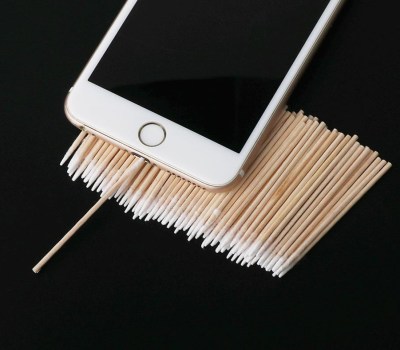
What if a socket on your phone or laptop fails? First off, it could be due to dust or debris. There’s swabs you can buy to clean a USB-C connector; perhaps adding some isopropyl alcohol or other cleaning-suitable liquids, you can get to a “good enough” state. You can also reflow pins on your connector, equipped with hot air or a sharp soldering iron tip, as well as some flux – when it comes to mechanical failures, this tends to remedy them, even for a short period of time.

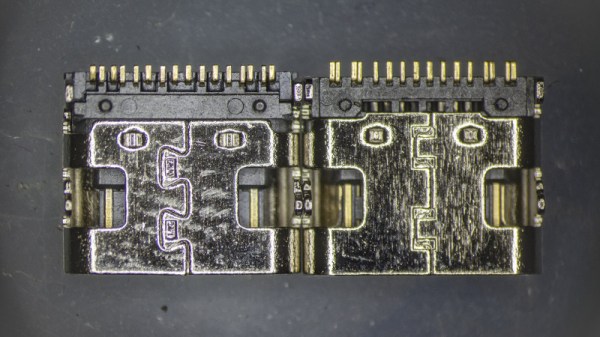
How could a connector fail, exactly? Well, one of the pins could break off inside the plastic, or just get too dirty to make contact. Consider a device with a USB-C charging and data socket, with USB 2.0 but without high-speed pairs – which is to say, sadly, the majority of the phones out there. Try plugging it into a USB-A charger using a USB-A to USB-C cable. Does it charge, even if slowly? Then, your VBUS pins are okay.

Plug it into a Type-C charger using a Type-C cable, and now the CC pins are involved. Does it charge in both orientations? Then both of your CC pins are okay. Does it charge in only one orientation? One of the CC pins has to be busted. Then, you can check USB 2.0 pins, used for data transfer and legacy charging. Plug the phone into a computer using a USB-A to USB-C cable. Does it enumerate as a device? Does it enumerate in both orientations? If not, you might want to clean D- and D+ pins specifically, maybe even both sets. Continue reading “All About USB-C: Connector Mechanics”

A Simple Web-Based Wiring Harness Tool

When building electronic assemblies there is quite often the need to construct custom cables to hook things up. It’s all very well if you’re prototyping by hand, or just building one or two of a thing, but if you’re cranking them out using outside help, then you’re going to want to ensure that cable is described very accurately. [Christian Nimako-Boateng Jr.] presents for us the first version of wirely, a wiring harness tool. This is a web-based tool that allows one to describe the cable ends and connectivity between them, producing a handy graphic and exports to excel in a format that should be easy to follow.

Based around the wireviz Python library running on a flask-based backend, image data are sent to the web assembly front-end and rendered with OpenGL. Configuration files can be imported and exported as JSON, making it easily linkable to other tools if required. Helpfully, the tool also seems to support some kind of revision control, although we didn’t try that yet. The process is straightforward enough, one simply defines a few groups (these relate to individual PCBs or other floating items in the assembly) which each contain one or more connectors. First, the connectors are described with part numbers, and wire gauge data, before defining the list of connections (wires) showing which signal and physical pins are connected together. Nothing more complex than that yet. We think there is still some more functionality that the tool could manage, such as shielding and guarding details, twisted pair definitions and a few others, but for a first pass, wirely looks pretty handy.

If you want a more heavyweight option using IEC 60617 symbols for describing wiring harnesses, then look no farther than QElectroTech, and yes, we have covered wireviz before, just for those that want to cut out the middleman and describe their cables in Python directly.

Remoticon 2021 // Debra Ansell Connects PCB In Ways You Didn’t Expect

“LEDs improve everything.” Words to live by. Most everything that Debra Ansell of [GeekMomProjects] makes is bright, bold, and blinky. But if you’re looking for a simple string of WS2812s, you’re barking up the wrong tree. In the last few years, Debra has been making larger and more complicated assemblies, and that has meant diving into the mechanical design of modular PCBs. In the process Debra has come up with some great techniques that you’ll be able to use in your own builds, which she shared with us in a presentation during the 2021 Hackaday Remoticon.

She starts off with a quick overview of the state of play in PCB art, specifically of the style that she’s into these days: three dimensional constructions where the physical PCB itself is a sculptural element of the project. She’s crossing that with the popular triangle-style wall hanging sculpture, and her own fascination with “inner glow” — side-illuminated acrylic diffusers. Then she starts taking us down the path of creating her own wall art in detail, and this is where you need to listen up. Continue reading “Remoticon 2021 // Debra Ansell Connects PCB In Ways You Didn’t Expect”

USB to Dupont adapter by [PROSCH]

USB Power Has Never Been Easier

USB cables inevitably fail and sometimes one end is reincarnated to power our solderless breadboards. Of course, if the cable broke once, it is waiting to crap out again. Too many have flimsy conductors that cannot withstand any torque and buckle when you push them into a socket. [PROSCH] has a superior answer that only takes a couple of minutes to print and up-cycles a pair of wires with DuPont connectors. The metal tips become the leads and the plastic sheathing aligns with the rim.

The model prints with a clear plus sign on the positive terminal, so you don’t have to worry about sending the wrong polarity, and it shouldn’t be difficult to add your own features, like a hoop for pulling it out, or an indicator LED and resistor. We’d like to see one with a tiny fuse holder.

If you want your breadboard to have old-school features, like a base and embedded power supply, we can point you in the right direction. If you are looking to up your prototyping game to make presentation-worthy pieces, we have a host of ideas.

What’s In A USB-C Connector?

Anyone who’s ever put together a bill-of-materials for an electronic device will be familiar with the process of scouring supplier catalogs and data sheets for the best choice of components. The trick is to score the best combination of price and performance for the final product, and for those unused to the process, there are always seemingly identical products with an astonishingly wide variety of prices. It’s a topic [Timon] explores in a Twitter thread, examining a 20-cent in quantity of 100 USB-C socket alongside one that costs only 5 cents, and his teardown provides a fascinating insight into their manufacture.

The parts look so nearly identical that while it’s possible to differentiate between them visually, it’s near impossible to work out which was the cheaper. Some tiny features such as a crack in a metal fold or a bit less plating on the contacts emerge, but even then it’s no guide to the quality as they don’t appear on the same part. It’s only when the metal shell is removed to expose the underlying plastic moulding that more clues emerge, as one moulding is more complex than the other. The more complex moulding provides a better and more reliable fit at the expense of a much more costly moulding process, so at last we can not only identify the more expensive part but also see where the extra cash has gone. It’s a subtle thing, but one that could make a huge difference to the performance of the final assembly and which makes for a fascinating expose for electronic design engineers.

If connectors are your thing, there’s a wealth of fascinating information in their history.

Odd-Sized Military Headphone Connectors, Tamed!

Military headphones, at least the older ones, are like few other sound reproducers. They are an expression of function over form, with an emphasis on robustness over operator comfort. Electrically they most often have high-impedance drivers and annoyingly proprietary connectors for whichever obscure radio system they were a part of.

[John Floren] has a HS-16A headset, the type used by the US military during the Vietnam war. It’s an antiquated design with a dual spring steel headband and on-the-ear ‘phones with no muff for comfort, and a quick bit of research finds that they can be had brand new in their 1960s packaging for somewhere around $20. Their connector is a pair of odd metal pins, and rather than doing what most of us would do and snipping the wire to fit something more useful, he hunted high and low for a TE Connectivity receptacle that would fit them. A short extension and a jack plug allowed him to use these slightly unusual cans.

This isn’t a special hack, but it’s still an interesting read because it sheds a bit of light upon these old-style headphones and reveals that they’re still available for anyone who wants their radio operating to have a retro feel. If you buy a set, you’ll probably still have them decades after more modern pairs have bitten the dust.

The (Unnecessary?) Art Of Connector Crimping

The “Completion Backwards Principle” is a method of reasoning through a problem by visualizing the end result and then working your way backwards from that point. The blog post that [Alan Hawse] has recently written about the intricacies of crimping wires for plug connectors is a perfect example of this principle. The end result of his work is the realization that you probably shouldn’t bother crimping your own connectors, but watching him work backwards from that point is still fascinating. It’s also the name of a rock album from the 80’s by The Tubes, but this is not a useful piece of information in regards to electrical wiring.

Of course, sometimes people do silly things. Even though there are pre-crimped wires available online for a pittance, you might still want to do your own. With this in mind, [Alan] has put together an exceptionally detailed and well-research post that gives you all the information you could possibly want to know about crimping what is often erroneously referred to as the “JST connector”.

He starts by showing off some common examples of this connector, which if you’ve ever opened a piece of consumer electronics will be like looking through a High School yearbook. You might not know their names without reading them, but you definitely remember what they look like.

We’re then treated to an array of macro shots showing the scale of the pieces involved. If getting up close and personal with metal bits that are only a few millimeters long is your kind of thing, then you’re really going to love this part.

Finally, the post is wrapped up with a few words about the kind of crimping tools that are available on the market, and then a demonstration of his personal crimping method. While some tools would have you crimp both sets of “wings” at the same time, [Alan] tells us he finds taking them on individually leads to better results in his experience.

If this this little taste has left you hungry for a true feast of hyper-specialized knowledge, be sure to check out the Superconference talk by [Bradley Gawthrop].

Continue reading “The (Unnecessary?) Art Of Connector Crimping”