Protect Yourself — And Your Project — While Working With Mains Power

When debugging ordinary low-voltage circuitry, you’re pretty safe: unless you have some really power-hungry devices that need a ton of current, there aren’t that many truly bad things that can happen, so you can take a lot of liberties with electrical-safety rules. With mains-powered devices, you don’t have this luxury, and a lack of knowledge, sloppy work practices, or simple mistakes can cost you — and your project — dearly. While you still need to know what you’re doing and use the requisite caution, [Yann Guidon]’s latest project — and entry in the 2019 Hackaday Prize —  a mains protection box, might keep simple mistakes from becoming a disaster.

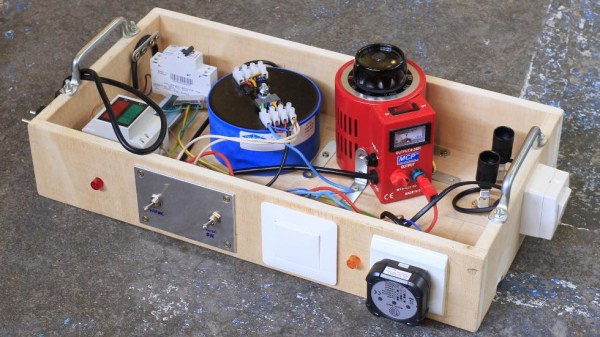
There are a number of precautions you can take when working with mains power. We’ve all used the simple in-line power strip so you can quickly switch off the current, but [Yann] has included a number of devices that can be configured in different ways to experiment with mains-powered devices safely. Built into a sturdy open-topped wooden box with carry handles, the project evokes the traditional breadboard in appearance and functionality. A number of different devices are included, which could be re-configured into different topologies if needed.

[Yann] included an isolation transformer, which can be useful not only for protection against shock in case of accidentally grounding, but also for noise suppression. There is also a variac, which allows the output voltage to be adjusted over a wide range for testing. Of course, circuit breakers are a must, and current and voltage meters keep you informed about what’s going on. A big, easy-to-access switch cuts the power quickly when needed.

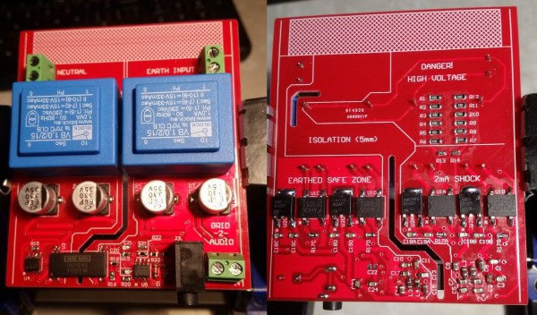
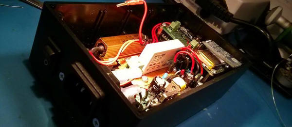
The (maybe) final touch is an adjustable output current limit, which is still a work in progress. Built around a current-monitoring relay and a DPDT relay wired as a latch, this allows the output to be disconnected if it draws more than a specified current, equivalent to between 10 W and 100 W. This is the perfect thing for initial testing of new projects.

So, if you’re thinking of working on mains-powered projects, have a close look at what [Yann] has assembled, and learn proper safety procedures before you begin. One place to start is with a great series by our own Jenny List about mains safety: part one and part two. Stay safe out there!

Listening To Mains Power, Part 2

The electricity on the power grid wherever you live in the world will now universally come to you as AC. That is to say that it will oscillate between positive and negative polarity many times every second. The frequency of 50 or 60Hz just happens to be within the frequency range for human hearing. There’s a lot more than this fundamental frequency in the spectrum on the power lines though, and to hear those additional frequencies better you’ll have to do a little bit of signal processing.

We first featured this build back when it was still in its prototyping phase, but since then it’s been completed and used successfully to find a number of anomalies on the local power grid. It takes inputs from the line, isolates them, and feeds them into MATLAB via a sound card where they can be analyzed for frequency content. It’s been completed, including a case, and there are now waterfall diagrams of “mystery” switching harmonics found with the device, plus plots of waveform variation over time. There’s also a video below that has these harmonics converted to audio so you can hear the electricity.

Since we featured it last, [David] also took some feedback from the comments on the first article and improved isolation distances on his PCB, as well as making further PCB enhancements before making the final version. If you’ve ever been curious as to what you might find on the power lines, be sure to take a look at the updates on the project’s page.

Continue reading “Listening To Mains Power, Part 2”

High Voltage Measurement Is Shockingly Safe

With the right equipment and training, it’s possible to safely work on energized power lines in the 500 kV range with bare hands. Most of us, though, don’t have the right equipment or training, and should take great care when working with any appreciable amount of voltage. If you want to safely measure even the voltages of the wiring in your house there’s still substantial danger, and you’ll want to take some precautions like using isolated amplifiers.

While there are other safe methods for measuring line voltage or protecting your oscilloscope, [Jason]’s isolated amplifier method uses high voltage capacitors to achieve isolation. The input is then digitized, sent across the capacitors, and then converted back to an analog signal on the other side. This project makes use of a chip from TI to provide the isolation, and [Jason] was able to build it on a perfboard while making many design considerations to ensure it’s as safe as possible, like encasing high voltage sections in epoxy and properly fusing the circuit.

[Jason] also discusses the limitations of this method of isolation on his site, and goes into a lot of technical details about the circuit as well. It probably wouldn’t get a UL certification, but the circuit performs well and even caught a local voltage sag while he was measuring the local power grid. If this method doesn’t meet all of your isolation needs, though, there are a lot of other ways to go about solving the problem.

Listening To Mains Power

There’s a lot you can tell by looking at the waveform of your mains power. There are harmonics, transient changes, and periodic fluctuations that are correlated to the demand on the grid itself. Frequency shifts will tell you how fast or slow your clocks are running, and someone probably has a poorly isolated power line communication thing somewhere in your neighborhood. There’s a lot you can learn by looking at the waveform coming out of your outlets, but how do you tap into that? [David] is doing it with a PC sound card and some really interesting hardware.

The Grid 2 Audio module is [David]’s entry to this year’s Hackaday Prize, and it consists of three main parts. The first is the mechanical part of the design. This comes in the form of an IEC power socket with a built-in switch, fuse, and illumination. Of course, you could simply buy one of these, but [David] is teaching himself Autodesk Inventor, and you have to start somewhere. The second part of this build is the PCB power supply and mains input. This is basically a pair of transformers, a PCB, and a whole lot of isolation to make this a safe board. The third part is a signal conditioning board that sends the waveform to a 3.5mm jack, for easy processing with any audio capture hardware.

The hardest part of this board is, by far, the PCB design, and for that [David] went all out. There are some big, meaty traces on this thing and real separation between the high voltage and low voltage portions of the board. The end result is something that sends the mains waveform to an audio card for easy processing with MATLAB, and all the goodies that come from that.

Prepping For Power Outages

When the mains power goes, we are abruptly brought face-to-face with how many of the devices and services we take for granted rely upon it. Telephones for instance, where once they were attached to the wall by a cable, now they are a cordless device with a mains-powered base station. Your cellphone can fill that gap, but a modern smartphone with a battery life of under a day is hardly a reliable long-term solution. Meanwhile modern heating systems may still burn gas or fuel oil, but rely on an electric pump for circulation. Your kitchen is full of electrically-powered white goods, your food is preserved by an electric refrigerator, even your gas cooker if you have one will probably expect a mains supply.

When the power goes out we might say that we instantaneously travel back a couple of centuries, but the reality is that our ancestors in 1817 wouldn’t have been in the same mess we are, they had appropriate solutions to surviving a wickedly cold winter when electricity was still something of a gleam in [Michael Faraday]’s eye. In short, they were prepared in a way most of us are not. That’s a shame, so let’s take a closer look sensible modern preparedness.

Continue reading “Prepping For Power Outages”

Mains Clocking A Microcontroller

[Lujji] is playing around with the STM8 microcontroller. In reviewing the official documentation for this chip, he read the external clock can be a sine wave, a triangle wave, or a square wave with a 50% duty cycle. The minimum CPU frequency is 0 Hz. [Lujji] doesn’t have a signal generator, and presumably, he’s all out of crystals. He does have mains AC, though, so why not clock a microcontroller with wall power?

Using mains power as a frequency standard is a concept a hundred years old. Synchronous motors turn at a rate proportional to the mains frequency, and this has been used in clocks for decades. If you’re really clever, you can clock digital circuits with mains AC, but we’ve never seen someone replace a tiny crystal in a microcontroller circuit with mains power.

After an experiment to prove the concept, [Lujji] went on to construct a circuit that wasn’t as dumb as connecting the microcontroller directly to a wall socket. The direct approach didn’t work that well anyway — the STM8 didn’t like low frequency clocks with slow edges. [Lujji] needed a clock with cleaner edges, and a 555 configured as a comparator fit the bill.

The completed circuit sends mains power through an optocoupler to drive a 555 configured as a comparator. The output is a clean 50Hz clock that is connected to the OSCIN pin on an STM8. This is now a chip running at 50Hz, and yes, it works. [Lujji] set up a circuit to write ‘Hello World’ on an old Nokia LCD. That took about three minutes. It works, though, even though it’s completely useless. Maybe this can be applied to some novel timekeeping similar to that one-instruction-per-day clock we looked earlier in the year.

Awesome Prank Or Circuit-Breaker Tester?

Many tools can be used either for good or for evil — it just depends on the person flipping the switch. (And their current level of mischievousness.) We’re giving [Callan] the benefit of the doubt here and assuming that he built his remote-controlled Residual Current Device (RDC) tripper for the purpose of testing the safety of the wiring in his own home. On the other hand, he does mention using it to shut off all the power in his house during an “unrelated countdown at a party”. See? Good and evil.

An RCD (or GFCI in the States) is a kind of circuit breaker that trips when the amount of current in the hot and neutral mains power lines aren’t equal and opposite, which would suggest that the juice was leaking out somewhere, hopefully not through someone. They only take a few milliamps of imbalance to blow so that nobody gets hurt. Making a device to test an RCD is easy; a resistor between hot and the protective ground circuit would do.

[Callan] over-engineers. He used a 50 W resistor where 30 W would do under the worst circumstances. A stealthy solid-state relay switches the resistor in, driven by an Uno and a Bluetooth module, so he can trip his circuit breakers from his smartphone, naturally.
Continue reading “Awesome Prank Or Circuit-Breaker Tester?”