Sketchy Logg Dogg Logging Robot Remote Control Hacking

When we last left [Wes] amidst the torn-open guts of his Logg Dogg logging robot, he had managed to revitalize the engine and dug into the hydraulics, but one big obstacle remained: the lack of the remote control unit. In today’s installment of the Logg Dogg series, [Wes] summarizes weeks of agony over creating a custom circuit based around a microcontroller, a joystick and a lot of relays and other bits and pieces to drive the solenoids inside the logging machine that control the hydraulics.

Giving the remote controller a bench test before connecting to the logging robot (Credit: Watch Wes Work)

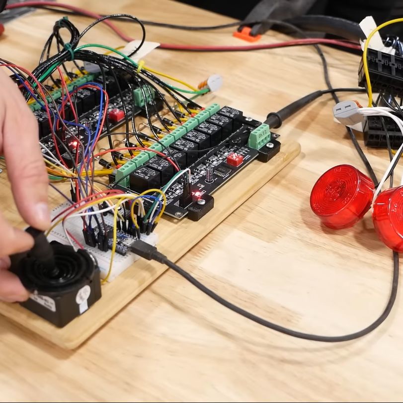
Most of the struggle was actually with the firmware, as it had to not only control the usual on/off solenoids, but also a number of proportional solenoid valves which control things like the track speed by varying the hydraulic flow to the final drives.

This requires a PWM signal, which [Wes] generated using two MOSFETs in a closed-feedback system, probably because open loop controls with multi-ton hydraulic machinery are not the kind of excitement most people look forward to.

Ultimately he did get it sorted, and was able to take the Logg Dogg for its first walk since being rescued from a barn, which both parties seemed to rather enjoy. The background details of this machine and the project can be found in our first coverage.

We’re looking anxiously forward to the next episode, where the controller goes wireless and the sketchiness gets dialed down some more.

Continue reading “Sketchy Logg Dogg Logging Robot Remote Control Hacking”

MOSFETs — The Hidden Gate

How many terminals does a MOSFET have? Trick question since most have three leads, even though there are really four connections to the underlying device. It isn’t a conspiracy, though and [Aaron Lanterman] talks about how MOSFETs really work and why thinking of them as three-terminal devices can lead you astray in a recent video that you can watch below.

Like many people, [Aaron] points out the parallel between a triode vacuum tube and a MOSFET. That’s not surprising, since a solid-state tube was exactly what they were looking for when they developed the FET. Since tubes and FETs are both voltage controllers, it is easy to think of the gate as the grid, the source as the cathode, and the drain as the plate. But, [Aaron] shows this isn’t really a very accurate picture.

Continue reading “MOSFETs — The Hidden Gate”

Spy Radio Setup Gets A Tiny Power Supply For Field Operations

[Helge Fyske (LA6NCA)] may not be an actual spy — then again, he may be; if he’s good at it, we wouldn’t know — but he has built a couple of neat vacuum tube spy radios in the past. And there’s no better test for such equipment than to haul it out into the field and try to make some contacts. But how do you power such things away from the bench?

To answer that question, skip ahead to the 3:18 mark of the video below, where [Helge] shows off his whole retro rig, including the compact 250-volt power supply he built for his two-tube 80-m Altoids tin spy transceiver. In the shack, [Helge] powers it with a bench power supply of his own design to provide the high anode voltage needed for the tubes, as well as 12 volts for their heaters. Portable operations require a more compact solution, preferably one that can be run off a battery small enough to pack in.

By building his power supply in a tin, [Helge] keeps to his compact build philosophy. But the circuit is all solid state, which is an interesting departure for him. The switch-mode supply uses a 4047 astable multivibrator chip as a 50-kHz oscillator, which switches back and forth between a pair of MOSFETs to drive a transformer. This steps up the 12-volt input to 280 volts AC, which is then rectified, filtered, and regulated to 250 volts DC.

To round out his spy rig, [Helge] also designed a tiny Morse key, which appears to be 3D printed and fits in its own tin, and a compact dipole antenna. Despite picking what appears to be a challenging location — the bottom of a steep-sided fjord — [Helge] was easily able to make contacts over a distance of 400 km. His noise floor was remarkably low, a testament to the solid design of his power supply. Including the sealed lead acid battery, the whole kit is compact and efficient, and it’s a nice example of what vacuum tubes and solid state can accomplish together.

Continue reading “Spy Radio Setup Gets A Tiny Power Supply For Field Operations”

Linear Power Supply’s Current Limiter Is A Lesson In Simplicity

Here at Hackaday we really like to feature projects that push the limits of what’s possible, or ones that feature some new and exciting technology that nobody has ever seen before. So what’s so exciting about this single-voltage linear power supply? Honestly, nothing — until you start looking at its thermally compensated current limiting circuit.

This one is by [DiodeGoneWild], who you’ve really got to hand it to in terms of both the empirical effort he went through to optimize the circuit, as well as the quality of his explanation. The basic circuit is dead simple: a transformer, a full-wave rectifier, an LD1085 adjustable regulator — a low-dropout version of the venerable LM317 — and associated filter caps and trimmer pot to adjust the output between 2.2 and 5.5 volts.

The current limiting circuit, though, is where things get interesting. Rather than use an op-amp, [DiodeGoneWild] chose a simple discrete transistor current-sense circuit. To make it less susceptible to thermal drift, he experimented with multiple configurations of resistors and Schottky diodes over a wide range of temperatures, from deep-freeze cold to hair-dryer-in-a-box hot. His data table and the resulting graph of current versus temperature are works of art, and they allowed him to make sensible component selections for a fixed 250-mA current limit with a reasonably flat thermal response.

As for construction, it’s all classic [DiodeGoneWild], including a PCB with traces ground out with a Dremel and a recycled heat sink. He also dropped a couple of interesting build techniques, like adding leads to turn SMD tantalum caps into through-hole components. The video below shows all the build details along with the exhaustive breadboard testing.

From taking on a potentially risky magnetron teardown to harvesting lasers from headlights, there’s always something to learn from a [DiodeGoneWild] video.

Continue reading “Linear Power Supply’s Current Limiter Is A Lesson In Simplicity”

Op-Amp Challenge: MOSFETs Make This Discrete Op Amp Tick

When it comes to our analog designs, op-amps tend to be just another jellybean part. We tend to spec whatever does the job, and don’t give much of a thought as to the internals. And while it doesn’t make much sense to roll your own op-amp out of discrete components, that doesn’t mean there isn’t plenty to be learned from doing just that.

While we’re more accustomed to seeing [Mitsuru Yamada]’s digital projects, he’s no stranger to the analog world. In fact, this project is a follow-on to his previous bipolar transistor op-amp, which we featured back in 2021. This design features MOSFETs rather than BJTs, but retains the same basic five-transistor topology as the previous work, with a differential pair input stage, a gain stage, and a buffer stage. Even the construction of the module is similar, using his trademark perfboard and ultra-tidy wiring.

Also new is a flexible evaluation unit for these discrete op-amp modules. This very sturdy-looking circuit provides an easy way to configure the op-amp for testing in inverting, non-inverting, and transimpedance mode, selecting from a range of feedback resistors, and even provides a photodiode input. The video below shows the eval unit in action with the CMOS module, as well as highlights the excellent construction [Mitsuru Yamada] is known for.

Looking for some digital goodness? Check out the PERSEUS-8, a 6502 machine we wish had been a real product back in the day.

Continue reading “Op-Amp Challenge: MOSFETs Make This Discrete Op Amp Tick”

Hackaday Links Column Banner

Hackaday Links: May 14, 2023

It’s been a while since we heard from Dmitry Rogozin, the always-entertaining former director of Roscosmos, the Russian space agency. Not content with sending mixed messages about the future of the ISS amid the ongoing war in Ukraine, or attempting to hack a mothballed German space telescope back into action, Rogozin is now spouting off that the Apollo moon landings never happened. His doubts about NASA’s seminal accomplishment apparently started while he was still head of Roscosmos when he tasked a group with looking into the Apollo landings. Rogozin’s conclusion from the data his team came back with isn’t especially creative; whereas some Apollo deniers go to great lengths to find “scientific proof” that we were never there, Rogozin just concluded that because NASA hasn’t ever repeated the feat, it must never have happened.

Continue reading “Hackaday Links: May 14, 2023”

FET: The Friendly Efficient Transistor

If you ever work with a circuit that controls a decent amount of current, you will often encounter a FET – a Field-Effect Transistor. Whether you want to control a couple of powerful LEDs, switch a USB device on and off, or drive a motor, somewhere in the picture, there’s usually a FET doing the heavy lifting. You might not be familiar with how a FET works, how to use one and what are the caveats – let’s go through the basics.

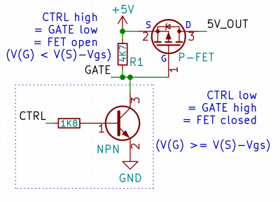
Here’s a simple FET circuit that lets you switch power to, say, a USB port, kind of like a valve that interrupts the current flow. This circuit uses a P-FET – to turn the power on, open the FET by bringing the GATE signal down to ground level, and to switch it off, close the FET by bringing the GATE back up, where the resistor holds it by default. If you want to control it from a 3.3 V MCU that can’t handle the high-side voltage on its pins, you can add a NPN transistor section as shown – this inverts the logic, making it into a more intuitive “high=on, low=off”, and, you no longer risk a GPIO!

This circuit is called a high-side switch – it enables you to toggle power to a device at will through a FET. It’s the most popular usecase for a FET, and if you’re wondering more about high-side switches, I highly recommend this brilliant article by our own [Bil Herd], where he shows you high-side switch basics in a simple and clear way. For this article, you can use this schematic as a reference of how FETs are typically used in a circuit.

Continue reading “FET: The Friendly Efficient Transistor”