EPROM Coffee Table

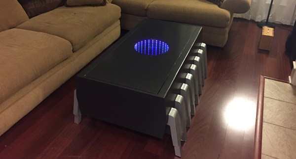
Either in need of a coffee table or suffering a severe lack of upscaled electronics, [Darren] just finished up a great build for his living room. It’s a huge, scaled up version of a UV erasable EPROM with an infinity mirror in place of the fused quartz window.

[Darren]’s coffee table was inspired by an earlier build by the geniuses at Evil Mad Scientist. A few years ago, they built a 555 footstool that was scaled up about 30 times its normal size. Even at footstool scale, the 555 is still relatively tiny.

[Darren] is using a similar construction technique by forming the legs of the EPROM out of laminated plywood. Since this build is significantly larger, building the entire device out of solid, laminated plywood would result in an unwieldy and expensive piece of furniture. Instead, [Darren] constructed the legs and sides out of plywood laminations, covering the ends, top, and bottom with plywood panels. The result is a hollow EPROM/coffee table that’s still structurally sound.

If you’re a bit confused after counting the number of pins on the coffee table, you’re in good company. This is technically a scaled-up version of a 16-pin 0.600″ PDIP, something that a quick googling suggest isn’t historically accurate. Maybe there was an EPROM with a 4-bit wide data bus somewhere in the annals of electronics history, but we’re happy with saying that a completely accurate scaled-up ROM would be far too big for [Darren]’s living room.

Continue reading “EPROM Coffee Table”

Improving A Modern Instant Camera

Instant film never went away – Fujifilm has been producing instant film for decades before Polaroid ceased production. Yes, cries of a lost photographic heritage were all for naught, and you can still buy an instant camera. [Dan] picked up a Fujifilm Instax Wide camera – an instant camera that produces not-square images – and figured some electronic tinkering could vastly expand the capabilities of this camera. He took it apart and made some modifications, giving it a bulb mode for long exposures and multi-exposure capability.

[Dan] began his tinkering by figuring out how to put multiple exposures on one frame of film. The Instax Wide camera has an eject sensor, a wire for the shutter button, and a few wires leading to the motor. By adding a switch to turn off the motor and a pushbutton to bypass the ejection sensor, [Dan] can stack multiple exposures on a single frame of film.

Multiple exposures are one thing, but how about longer exposures for light painting and all those other cool things you can do with microcontrolled LEDs? Modding the camera for that is pretty easy. All you need are a few mini toggle switches. It’s just a simple matter of opening the shutter for as long as you need, painting a scene with light, and flipping a few more switches to eject the film. [Dan] is getting some pretty respectable exposures with this – somewhat impressive considering the camera’s fixed aperture.

Downloading Data Through The Display

HIPAA – the US standard for electronic health care documentation – spends a lot of verbiage and bureaucratese on the security of electronic records, making a clear distinction between the use of records by health care worker and the disclosure of records by health care workers. Likewise, the Federal Information Security Management Act of 2002 makes the same distinction; records that should never be disclosed or transmitted should be used on systems that are disconnected from networks.

This distinction between use and disclosure or transmission is of course a farce; if you can display something on a screen, it can be transmitted. [Ian Latter] just gave a talk at Kiwicon that provides the tools to do just that. He calls it ThruGlassXfer (TGXf), and it does exactly what it says on the tin: anything that can be displayed on a screen can be transmitted. All you need are the right tools.

Continue reading “Downloading Data Through The Display”

Sqonkbox 55 Is A Cigar Box Organ Of Awesome

Sometimes, the best birthday presents are the ones you give yourself. In [Dino]’s case, they’re the ones you make for yourself.  In honor of his 55th, he built the Sqonkbox 55, a 13-note cigar box organ based on a 555 and amplified with an LM386.

It’s based on a 555 wired in astable mode, turning it into an oscillator that outputs a frequency. This frequency is determined by the resistors between pins 6 and 7, another between 7 and 8, and the capacitor between pin 2 and ground. [Dino] shows a breadboard version first, with a single tuning pot and momentary acting as a piano key. As he explains, this portion of the circuit is repeated 13 times with pots and momentaries that he arranges like piano keys through the lid of a cigar box.

“Sqonkbox,” you ask? A second 555 in astable mode sends the output through an LED. This LED stands face to face with an LDR, and they are shrouded in this configuration with black heat shrink tubing. The ‘sqonk’ 555 changes the frequency of the first 555, providing a clippy, rhythmic tone at the rate set by a potentiometer. [Dino]’s full video of the build is after the break. A BOM is forthcoming, but it’s easy enough to puzzle it out between the video and the lovely, Forrest Mims-esque schematicContinue reading “Sqonkbox 55 Is A Cigar Box Organ Of Awesome”

Redlining Your CPU Via Automotive Tachometer

Many CPU-usage widgets have stylistically borrowed from vehicles, displaying something mimicking the tachometer found in the dashboard. [Pat] took it a step further and tried his hand at re-borrowing this style. He figured, why not use an actual physical tachometer to display how hard the CPU on his Raspberry Pi was revving?

With the goal of tuning 0-100% CPU usage to 0-8000 RPM on the tach, the first step was diagnosing the range of PWM input frequencies that moved the needle across the tach’s full arc. Using his Tektronix 3252C function generator he quickly determined 0-440 Hz would be needed and graphed a handful of intermediate points. The response curve was not linear, so he drew up some fudging guidelines to make all the datapoints match.

Next, he wrote a few lines of Python (he shared) to make the Pi to poll its CPU usage and translate it to the proper frequency. The Pi makes outputting easy, GPIO pin 11 carried the signal to a 7404 for buffering, then out to the tach. The automotive tach itself ran on 12V, but its input signal required only 5V so he pulled a 7805 from his parts bin.

Once it was all put together it worked beautifully using just the one extra component. Some might see this as more clever than USB dependent or Arduino bloated based tachometer hacks.

See the video after the break of the tach twitching even when the mouse moved, and pegging the red when opening a browser. No more need to use up valuable screen real-estate (or use a screen at all) if you want to see at a glance when your Pi is putting in work.

Continue reading “Redlining Your CPU Via Automotive Tachometer”

nixieclock

Simple And Elegant Single Digit Nixie Tube Clock

We’ve seen a few Nixie projects around here before, but this one might be the simplest yet. [Pinomelean] designed this simple nixie tube clock with just a handful of components.

The Nixie tube chosen for the project is an IN-12a. This tube can be purchased for around just four dollars. It is capable of displaying one digit at a time, zero through nine. Since the tube can only display one digit at a time, the clock is programmed to flash each digit of the current time one by one. There is a longer pause in between each cycle to make it easier to tell when the cycle begins and ends.

The system is broken into two main components. The first is the clock circuit. The clock runs off a PIC microcontroller with a 4MHz crystal. All of the logic is performed via the PIC and only a handful of other components are required. This includes some resistors and capacitors as well as a few high voltage SMD transistors to control the Nixie tube. [Pinomelean] has made this PCB design available so anyone can download it and make their own clock.

The second component to the clock is the power supply. The system is powered by a lithium-ion rechargeable battery, but [Pinomelean] notes that it can also be powered with USB. The lower voltage works well for the microcontroller, but the Nixie tube needs a higher voltage. [Pinomelean] built his own high voltage supply using components scavenged from an old disposable camera. This power supply board design is also made available for download, but it plugs into the main board so you can use another design if desired.. Check out the demo video below to see it in action. Continue reading “Simple And Elegant Single Digit Nixie Tube Clock”

1.37″ CRT Restored By Hacklab For Miniature MAME Cabinet

For $5, [William] of Toronto’s Hacklab hackerspace got a hold of one of the smallest CRT screens ever made – about the size of a large coin. Over the course of a couple sessions – including a public hack boothside at their Mini Makerfaire – [William], [Igor], and several other members managed to connect it as a monitor directly off a Raspberry Pi. The end-goal is the world’s smallest MAME cabinet (smaller by almost half than this LCD one).

As Canada followed the US and stopped broadcasting analog back in 2011, it became quite a challenge to feed the screen a video source. They disclosed early that the easiest solution would just be an RF transmitter on the Pi and then tune the micro-set to that channel. Too easy. They wanted something elegant and challenging so they went digging into the circuitry to find a place to insert a composite video signal directly.

The real story here is their persistence at reverse engineering. The PCB was folded like a cardboard box to fit in the original case, making large portions of the circuitboard and wiring inaccessible. Even when they managed to trace the signal to what they thought was the appropriate chip (marked C80580), they could not find any information on the 30 year old chip. Noting that every other chip on the board was Panasonic and started with “AN5”, [Igor] suspected the mystery silicon was just renamed and went through every single datasheet he could find with that prefix. Combined with form factor, pin count and purpose, his sleuthing was rewarded with a guess for a match – the AN5715. His hunch was correct – using that datasheet led him to the answers they required.

Then they just had to figure out how get the composite signal the Pi outputted into something the chip would use to display the correct image. There were no shortage of challenges, failures and dead ends here either, but they had help from the rest of their membership.

Their project log is an interesting narrative through the process and in the end of course, it worked. It is displayed beautifully with a clear acrylic case and ready for a cabinet to be built.