Hackaday Prize Entry: Tearing Down A Tesla

We’ve seen a few people tear down the drive trains from electric vehicles like the Nissan Leaf, Prisuses, or the Chevy Volt. We’ve also seen someone tear down the battery pack found in a Tesla Model S. What we haven’t seen until now is a reverse engineering of the Tesla Model S drive train.

A fortuitous circumstance landed [Michal] the crown jewel of the Tesla Model S – the 310kW, 590Nm drive train. Exactly how and where [Michal] landed this gigantic powerful motor is a question that remains unanswered, and the question unasked. We might not want to know.

Now that he has a motor, the name of the game is figuring out how to drive it. Usually that means capturing data from the CAN bus and replaying that data. This isn’t what [Michal] is doing; instead, he’s using a motor controller he developed for the Chevy Volt and Toyota Prius. It’s going to be a lot of work, but that’s only because these gigantic EV motors and controllers are pretty rare on the used market now. Give it a few years, and the work [Michal] is putting in now will pay off in hundreds of DIY electric vehicles.


The 2015 Hackaday Prize is sponsored by:

Ask Hackaday (And Adafruit): The New CEO Of MakerBot

Just a few years ago, MakerBot was the darling of the Open Hardware community. Somehow, in the middle of a garage in Brooklyn, a trio of engineers and entrepreneurs became a modern-day Prometheus, capturing a burgeoning technology into a compact, easy to use, and intoxicating product. A media darling was created, a disruptive technology was popularized, and an episode of the Colbert Report was taped.

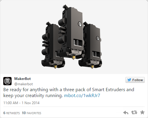
The phrase ‘meteoric rise’ doesn’t make sense, and since then the reputation of MakerBot has fallen through the floor, crashed through the basement, and is now lodged in one of the higher circles of hell. It’s not surprising; MakerBot took creations from their 3D object hosting site, Thingiverse, and patented them. The once-Open Source line of 3D printers was locked up behind a closed license. The new MakerBot extruder – the Smart Extruder – is so failure prone MakerBot offers a three pack, just so you’ll always have a replacement on hand. False comparisons to Apple abound; Apple contributes to Open Source projects. The only other way for a company to lose the support of the community built around it so quickly would be a name change to Puppy Kickers, LLC.

In the last few months, figurehead CEO of MakerBot [Bre Pettis] was released from contractual obligations, and MakerBot’s parent company, Stratasys, has filled the executive ranks with more traditional business types. It appears PR and Marketing managers have noticed the bile slung at their doorstep, and now MakerBot is reaching out to the community. Their new CEO, [Jonathan Jaglom] specifically requested a hot seat be built at Adafruit for an open discussion and listening meeting. Yes, this means Makerbot is trying to get back on track, winning the hearts and minds of potential customers, and addressing issues Internet forums repeat ad nauseam.

If you’ve ever wanted to ask a CEO how they plan to stop screwing things up, this is your chance. Adafruit is looking for some direction for their interview/listening meeting, and they’re asking the community for the most pressing issues facing the 3D printing community, the Open Source community, and MakerBot the company.

Already on the docket are questions about MakerBot and Open Source, MakerBot’s desire to put DRM in filament, the horrors of the Smart Extruder and the 5th generation MakerBots, problems with Thingiverse, and the general shitty way MakerBot treats its resellers.

This isn’t all Adafruit wants to ask; the gloves are off, nothing is off the table, and they’re looking for questions from the community. What would you like to ask the MakerBot CEO?

Personally, the best interview questions are when the interviewee’s own words are turned around on them. By [Jonathan Jaglom]’s own admission, the barrier to entry for 3D design work has been substantially lowered in the last three years, ostensibly because of incredible advances in Open Source projects. Following this, do MakerBot and Stratasys owe a debt to Open Source projects, and should Stratasys contribute to the rising tide of Open Source development?

That’s just one question. There will, of course, be many more. Leave them down in the comments. “You are not [Tim Cook],” while a valid statement in many respects, is not a question.

Mini Arc Furnace Melts Its Way Into Our Hearts

[Grant Thompson], aka “The King of Random,” threw caution to the wind when it came to his latest awesome project – a mini electric arc furnace (EAF) (YouTube link). [Grant] uses a refractory brick as a furnace and crucible for the molten metal.  He wears eye protection and a respiratory mask as he cuts up the brick – a good idea, since you don’t want to inhale any of that dust. The electrode grips are made with things you can find at a hardware store, including copper wire and coupling, and 2 pairs of vice-grip style pliers. The copper wire is stripped and attached to the metal handle of the pliers using hose clamps. The pliers are now functional electrode grips- just put a carbon rod in each grip and hold them close to each other…but not without protection! [Grant] harvested the carbon rods  from the cells of 6V lantern batteries – dead batteries work just as well for this. It’s also a better bet to do this outdoors with decent ventilation and away from anything flammable. [Grant] realized that the rods from the batteries have a wax-like coating on them that takes about 30 seconds to burn off in spectacular flames the first time they make electrical contact. However, you can purchase carbon rods by themselves if you want to avoid ripping open batteries and possibly setting yourself on fire. The mini EAF runs on a welding power supply [Grant] made from microwave oven transformers  (YouTube link).

When it’s time to melt some metal, the scrap metal is placed into a bowl drilled into the brick. Using the electrode grips, the carbon rods are placed into the brick’s pre-drilled holes. It only takes ten seconds to melt pure zinc – do NOT do this with galvanized steel or brass castings, as zinc oxide is very hazardous to your health.

In the videos featured below, [Grant] shows a variety of metals are no match for his mini EAF. He even manages to melt rocks from his backyard! It goes without saying that an EAF (video link) can be very dangerous. When you’re dealing with high voltage, plasma, white-hot molten metal, and toxic fumes, you better know what you’re doing (or have a great life insurance policy). [Grant] has a penchant for showcasing projects that can make an OSHA inspector cringe,  but you have to admire his gumption!

Continue reading “Mini Arc Furnace Melts Its Way Into Our Hearts”

A Game Pad For The Apple II

[Quinn Dunki] has been hard at work building a Teddy Top – an Apple IIc Plus modified for a road warrior. It has a 3.5 inch disk drive, runs at a blistering four megahertz, and has a beautiful integrated color LCD. It would be a shame to have such a great machine and no way to play games as they were intended, so [Quinn] set about building a game pad for her lovable Apple II.

The Apple II joystick port isn’t as simple as an Atari or Commodore joystick port. Where the bog-standard Atari joystick is basically just a bunch of switches connected to pins, the Apple II joystick is analog. Weird, and even weirder is the value of the pots in these joysticks: 150kΩ. Somehow or another, nobody makes pots in this value any more. Luckily the hardware in these joysticks is well documented, and shoehorning in modern components isn’t that bad.

The Apple joystick has a bit of circuitry – a 556 timer chip that reads the values of each pot and converts that into a stream of 0s and 1s for the Apple. The joystick [Quinn] found for her game pad is an analog thumb stick on a neat breakout board manufactured by Parallax. This analog joystick has 10kΩ pots in it, and that just won’t work with the 556 timer chip. However, since this is just resistors and a 556 chip, adjusting some of the values on the original schematics does the trick. [Quinn] added a few capacitors to her circuit, and everything worked beautifully.

With the electronics down, she turned her attention to the case for her Apple II road warrior enclosure. She recently picked up a 3D printer, which means she’s new to 3D printing. After spending a few hours designing a controller in 123D Design, she sent the files over to the printer. Warping happened. She tried an ABS slurry. The part was stuck to the bed. It took a few tries (purple glue sticks are awesome, [Quinn]), but she eventually got her plastic enclosure printed out, and the circuitry installed. The result is a portable computer, with a custom controller, playing Lode Runner. Can’t beat that.

Retrotechtacular: Making Porcelain Insulators

Here is a silent film produced by General Electric that depicts the making of many kinds of porcelain insulators for power lines. Skilled craftsmen molded, shaped, and carved these vital components of the electrical grid by hand before glazing and firing them.

Porcelain insulators of this time period were made from china clay, ball clay, flint, and feldspar. In the dry process, ingredients are pulverized and screened to a fine powder and then pressed into molds, often with Play-Doh Fun Factory-type effects. Once molded, they are trimmed by hand to remove fins and flashing. The pieces are then spray-glazed while spinning on a vertical lathe.

Other types of insulators are produced through the wet process. The clay is mixed in a pug mill, which is a forgiving machine that takes scrap material of all shapes, sizes, and moisture levels and squeezes out wet, workable material in a big log. Chunks of log are formed on a pottery wheel or pressed into a mold. Once they are nearly dry, the pieces get their final shape at the hands of a master. They are then glazed and fired in a giant, high-temperature kiln.

Continue reading “Retrotechtacular: Making Porcelain Insulators”

Phonographs Through The Eye Of An Electron Microscope

Hackaday Prize judge [Ben Krasnow] has been busy lately. He’s put his scanning electron microscope (SEM) to work creating an animation of a phonograph needle playing a record. (YouTube link) This is the same 80’s SEM [Ben] hacked back in November. Unfortunately, [Ben’s]  JSM-T200 isn’t quite large enough to hold an entire 12″ LP, so he had to cut a small section of a record out. The vinyl mods weren’t done there though. SEMs need a conductive surface for imagingphono_anim_1
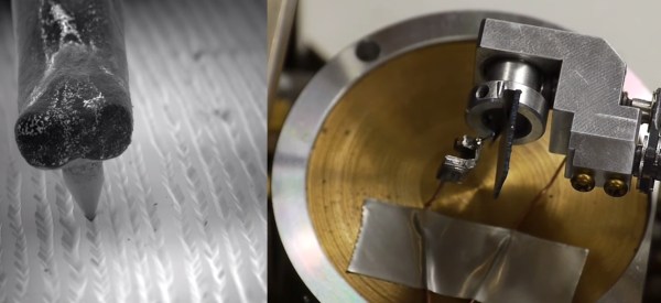
. Vinyl is an insulator. [Ben] dealt with this by using his vacuum chamber to evaporate a thin layer of silver on the vinyl.

Just imaging the record wouldn’t be enough; [Ben] wanted an animation of a needle traveling through the record grove. He tore apart an old phonograph needle and installed it in on a copper wire in the SEM. Thanks to the dual stage setup of the JSM-T200, [Ben] was able to move the record-chip and needle independently. He could then move the record underneath the needle as if it were actually playing. [Ben] used his oscilloscope to record 60 frames, each spaced 50 microns apart. He used octave to process the data, and wound up with the awesome GIF animation you see on the left. 

pits
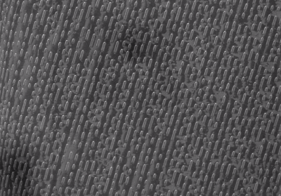
[Ben] wasn’t done though. He checked out a few other recording formats, including CD and DVD optical media, and capacitance electronic disc, an obscure format from RCA which failed miserably in the market. The toughest challenge [Ben] faced was imaging the CD media. The familiar pits of a CD are stored on a thin aluminum layer sandwiched between the lacquer label and the plastic disc. He tried dissolving the plastic with chemicals, but enough plastic was left behind to distort the image. The solution turned out to be double-sided tape. Sticking some tape down on the CD and peeling it off cleanly removed the aluminum, and provided a sturdy substrate with which to mount the sample in the SEM.

We’re curious if stereo audio data can be extracted from the SEM images.  [Oona] managed to do this with a mono recording from a toy robot.  Who’s going to be the first one to break out the image analysis software and capture some audio from [Ben’s] images?

Continue reading “Phonographs Through The Eye Of An Electron Microscope”

Prevent Failed Prints With A Filament Speed Sensor

If you have used a 3D printer for any length of time, you’ve probably experienced a failed print caused by a clogged nozzle. If you’re not around to stop the print and the nozzle stays hot and full of filament for hours, the clog gets even worse. [Florian] set out to solve this issue with an encoder that measures filament speed, which acts as an early warning system for nozzle clogs.

static1.squarespace.com
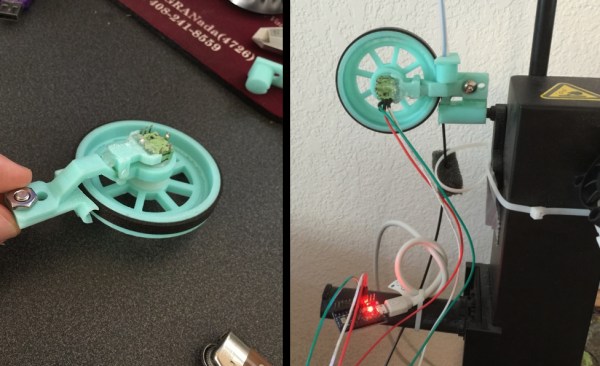
[Florian] designed a small assembly with a wheel and encoder that measures filament movement. The filament passes under the encoder wheel before it’s fed into the 3D printer. The encoder is hooked up to an Arduino which measures the Gray code pulses as the encoder rotates, and the encoder count is streamed over the serial port to a computer.

When the filament slows down or stops due to a nozzle clog, the Python script plays a notification sound to let you know that you should check your nozzle and that your print might fail. Once [Florian] works out some of the kinks in his setup, it would be awesome if the script could stop the print when the nozzle fails. Have any other ideas on how to detect print failures? Let us know in the comments.