How I²C EEPROM Talks To The Bus

You will probably be familiar with I²C, a serial bus typically used for not-very-fast communication with microcontroller peripherals. It’s likely though that unless you are an I²C wizard you won’t be intimately familiar with the intricacies of its operation, and each new device will bring a lengthy spell of studying data sheets and head-scratching.

If the previous paragraph describes you, read on. [Clint Stevenson] wrote a library for interfacing I²C EEPROMs to Arduino platforms, and when a user found a bug when using it on an ATtiny85, he wrote up his solution. The resulting piece is a clear explanation of how I²C EEPROMs talk to the bus, the various operations you can perform on them, and the overhead each places on the bus. He then goes on to explain EEPROM timing, and how since it takes the device a while to perform each task, the microcontroller must be sure it has completed before moving to the next one.

In the case of [Clint]’s library, the problem turned out to be a minor incompatibility with the Arduino Wire library over handling I²C start conditions. I²C has a clock and a data line, both of which are high when no tasks are being performed. A start condition indicates to the devices on the bus that something is about to happen, and is indicated by the data line going low while the clock line stays high for a while before the clock line starts up and the data line carries the I²C command. He’s posted samples of code on the page linked above, and you can find his library in his GitHub repository.

If you want to know more about I²C, take a look at Hackaday Editor [Elliot Williams’] masterclasses on the subject: What could go wrong, I²C edition, and Embed With Elliot, I²C bus scanning.

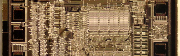
Serial EEPROM die picture, By Epop (Own work) [CC0], via Wikimedia Commons.

Inventables Releases Improved X-Carve CNC Router

Introduced last year as an improvement on the very popular Shapeoko CNC router, the X-Carve by Inventables has grown to be a very well-respected machine in the community. It’s even better if you throw a DeWalt spindle on there, allowing you to cut almost everything that’s not steel. With a recent upgrade to the X-Carve, it’s even more capable, featuring the best mods and suggestions from the community that has grown up around this machine.

The newest iteration of the X-Carve features higher power drivers, better rigidity, and a heat sink for the spindle. That last item is an interesting bit of kit – routing takes time, and a 1¼HP motor will turn electricity into heat very effectively.

X-CarveIn addition to the 500mm square and 1000mmm square routers previously available, there’s a new, 750mm square machine available. All machines feature a new electronics box for the X-Carve, the X-Controller. This ‘brain box’ is a combined power supply, stepper driver, and motion controller built into a single box. The stepper drivers are able to supply 4A to a motor, is capable of 1/16 microstepping, and has connections for limit switches, spindle control speed, a Z probe, and outputs for vacuums or coolant systems. The underlying controller is based on grbl, making this brain box a very solid foundation for any 3-axis CNC build. The ‘brain box’ format seems to be the way the hobbyist CNC market is going, considering the whispers and rumors concerning Lulzbot selling their Taz6 brainbox independently from a 3D printer.

The new X-Carve is available now, with a fully-loaded 1000mm wide machine coming in at about $1400. That’s comparable to many other machines with the same volume, unlike the Chinese 3040 CNC machines, you don’t need to find an old laptop with a parallel port.

Hackaday Prize Entry: Open Sip And Puff

A sip-and-puff device is an assistive technology used by people who cannot use their hands. Being a quasi-medical device, you can imagine this technology is extremely expensive, incapable of being modified, and basically a black box that can’t do anything except what it was designed for. For his Hackaday Prize entry, [Jason] is building his own sip-and-puff interface that’s cheaper and more capable than the available commercial versions.

Sip-and-puff devices can be mapped to control a wheelchair, click a mouse, or press a key on a keyboard. You can do a lot with USB, so for this open sip-and-puff device, [Jason] is using the ever-popular ATmega32U4 microcontroller.

USB is only one part of the problem, and to measure the sips and puffs of air through a plastic hose, [Jason] is using a pressure sensor from Freescale/NXP. While this is very similar to what would be found in the off-the-shelf version of a sip-and-puff device, it’s rather hard to interface with. The current version of the board is using an instrument amplifier, and the mechanical connection between the pressure sensor and the board is slightly bizarre. [Jason] has a few ideas for a better sensor, and for the rest of the Hackaday Prize he’s going to work on redesigning this device with simplicity in mind.

Antenna Rotation Arduino Style

Back in the days when you didn’t pay for your TV programming, it was common to have a yagi antenna on the roof. If you were lucky enough to have every TV station in the area in the same direction, you could just point the antenna and forget it. If you didn’t, you needed an antenna rotator. These days, rotators are more often found on communication antennas like ham radio beams. For terrestrial use, the antenna only needs to swing around and doesn’t need to change elevation. However, it does take a stout motor because wind loading can put a lot of force on the system.

[SP3TYF] has a HyGain AR-303 rotator and decided to build an Arduino-based controller for it. The finished product has an LCD and is able to drive a 24 V motor. You can control the azimuth of the antenna with a knob or via the computer.

Continue reading “Antenna Rotation Arduino Style”

Internet Of Things Woodworking

Woodworking is the fine art of building jigs. Even though we have Internet-connected toasters, thermostats, cars, and coffee makers, the Internet of Things hasn’t really appeared in the woodshop quite yet. That’s changing, though, and [Ben Brandt]’s Internet of Things box joint jig shows off exactly what cheap computers with a connection to the Internet can do. He’s fully automated the process of making box joints, all with the help of a stepper motor and a Raspberry Pi.

[Ben]’s electronic box joint jig is heavily inspired by [Matthias Wandel]’s fantastic screw advance box joint jig. [Matthias]’ build, which has become one of the ‘must build’ jigs in the modern woodshop, uses wooden gears to advance the carriage and stock across the kerf of a saw blade. It works fantastically, but to use this manual version correctly, you need to do a bit of math before hand, and in the worst-case scenario, cut another gear on the bandsaw.

[Ben]’s electronic box joint jig doesn’t use gears to move a piece of stock along a threaded rod. Stepper motors are cheap, after all, and with a Raspberry Pi, a stepper motor driver, a couple of limit switches, and a few LEDs, [Ben] built an Internet-enabled box joint jig that’s able to create perfect joints.

The build uses a Raspberry Pi 3 and Windows IoT Core to serve up a web page where different box joint profiles are stored. By lining the workpiece up with the blade and pressing start, this electronic box joint jig automatically advances the carriage to the next required cut. All [Ben] needs to do is watch the red and green LEDs and push the sled back and forth.

You can check out [Ben]’s video below. Thanks [Michael] for the tip.

Continue reading “Internet Of Things Woodworking”

The Evolution Of A DIY Circuit Board Plotter

In this three part video series we watch [Dirk Herrendoerfer] go from scraps to a nice 3D printed assembly as he iterates through the design of a pen plotter for making circuit boards.

[dana] mentioned [Dirk]’s work in the comments of this post which describes a different process. Many permanent markers stick to copper well enough to last through the chemical etching process. While hand drawing definitely produces some cool, organic-looking boards, for sharp lines and SMDs it gets a bit harder; to the point where it becomes advisable to just let a robot do it.

Of course, [Dirk] was aware of this fact of life. He just didn’t have a robot on hand. He did have some electronic detritus, fishing line, an Arduino, scrap wood, brass tubes, and determination.  The first version‘s frame consisted of wooden blocks set on their ends with holes drilled to accept brass rods. The carriage was protoboard and hot glue. Slightly larger brass tubing served as bushings and guide. As primitive as it was the plotter performed admirably, albeit slowly.

The second version was a mechanical improvement over the first, but largely the same. The software got a nice improvement. It worked better and had some speed to it.

The latest version has some fancy software upgrades; such as acceleration. The frame has gone from random bits of shop trash to a nicely refined 3D printed assembly. Even the steppers have been changed to the popular 28BYJ-48 series. All the files, software and hardware, are available on GitHub. The three videos are viewable after the break. It’s a great example of what a good hacker can put together for practically no money.

Continue reading “The Evolution Of A DIY Circuit Board Plotter”

NES Light Gun Fires Awesome Laser Effect

[Seb Lee-Delisle]’s NES lightgun gave us pause as the effect is so cool we couldn’t quite figure out how he was doing it at first. When he pulls the trigger there erupts the beam of light Sci Fi has trained us to expect, then it explodes in a precision sunburst of laserlight at the other end as smoke gently trails from the end of the barrel. This is a masterpiece of hardware and trickery.

seb-lee-delisle-nes-zapper-trick-thumb
Demo video posted by @seb_ly

The gun itself is a gutted Nintendo accessory. It looks like gun’s added bits consist of two LED strips, a laser module (cleverly centered with two round heatsinks), a vape module from an e-cigarette, a tiny blower, and a Teensy.  When he pulls the trigger a cascade happens: green light runs down the side using the LEDs and the vape module forms a cloud of smoke in a burst pushed by the motor. Finally the laser fires as the LEDs finish their travel, creating the illusion.

More impressively, a camera, computer, and 4W Laser are waiting and watching. When they see the gun fire they estimate its position and angle. Then they draw a laser sunburst on the wall where the laser hits. Very cool! [Seb] is well known for doing incredible things with high-powered lasers. He gave a fantastic talk on his work during the Hackaday Belgrade conference in April. Check that out after the break.

So what does he have planned for this laser zapper? Laser Duck Hunt anyone? He has a show in a month called Hacked On Classics where this build will be featured as part of the Brighton Digital Festival.

Continue reading “NES Light Gun Fires Awesome Laser Effect”