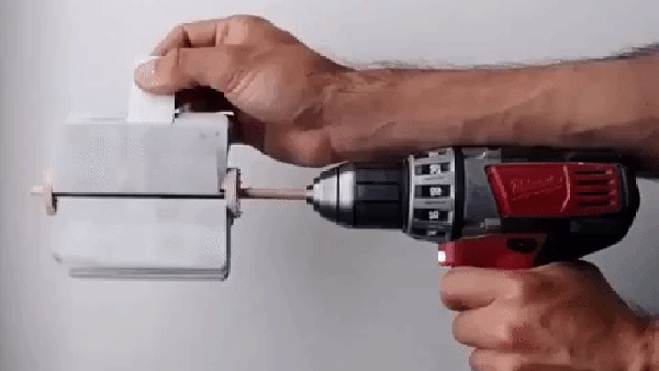
[WolfCat] of Wolfcatworkshop is creating a hand-animated split-flap animation. But what do you use to test your animation once it’s on the split-flaps? Well, to test it out, [WolfCat] used a drill to give it motion. DoodlersAnonymous has some pics and an interview with [WolfCat] about his animation and there are some pictures on his Instagram page.
Technically, what [WolfCat] wanted to make is a “mutoscope,” a hand-cranked precursor to the movie projector that had its heyday in the late 19th and early 20th century. Originally installed in penny arcades and the like, mutoscopes were single-viewer apparatus. The viewer cranks the handle and the animated cards inside rotate around, stopped briefly by a bit of metal at the top in order to show a frame. The basic idea is similar to the way split-flap clocks or signs work.
[WolfCat] hand drew the animation for his movie and then scanned and printed out each frame. The frames were then transferred to a pair of flaps. [WolfCat] wanted to see how it would look when animated, but didn’t have any plans at the time for a case or a hand crank, so he found the closest tool that would do the job – a cordless drill. Attaching the drill and using a bit of card or wood as a stopper, [WolfCat] could see how the end result would look and could then start work on the case and crank.
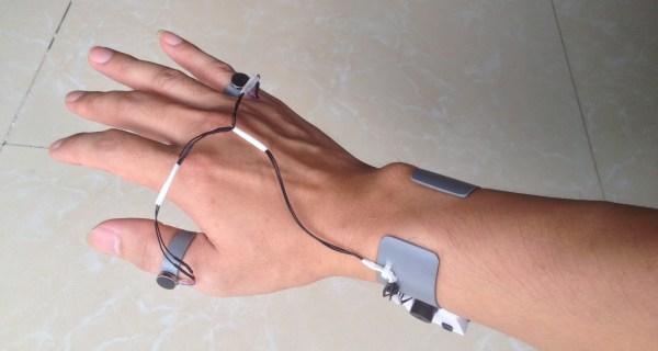
The World Health Organization estimates that around 90% of the 285 million or so visually impaired people worldwide live in low-income situations with little or no access to assistive technology. For his Hackaday Prize entry, [Tiendo] has created a simple and easily reproducible way-finding device for people with reduced vision: a bracelet that detects nearby objects and alerts the wearer to them.
It does its job using an ultrasonic distance sensor and an Arduino Pro Mini. The bracelet has two feedback modes: audio and haptic. In audio mode, the bracelet will begin to beep when an object is within 2.5 meters. And it behaves the way you’d expect—get closer to the object and the beeping increases; back away and it decreases. Haptic mode involves two tiny vibrating disk motors attached to small PVC cuffs that fit on the thumb and pinky. These motors will buzz differently based on the person’s proximity to a given object. If an object is 1 to 2.5 meters away, the pinky motor will vibrate. Closer than that, and it switches over to the thumb motor.
To add to the thriftiness of this project, [Tiendo] re-used other objects where he could. The base of the bracelet is a cuff made from PVC. The nylon chin strap and plastic buckle from a broken bike helmet make it adjustable to fit any wrist. To keep the PVC cuff from chafing, he slipped small pieces from an old pair of socks on to the sides.
It’s easy to see why this project is a finalist in our Best Product contest. It’s a simple, low-cost assistive device made from readily available and recycled materials, and it can be built by anyone who knows a little bit about electronics. Add in the fact that it’s lightweight and frees up both hands, and you have a great product that can help a lot of people. Watch it beep and buzz after the break. Continue reading “Hackaday Prize Entry: A Bracelet For The Blind”→
Let’s face it — the design of most home foundries leaves something to be desired. Most foundries are great at melting metal, but when it comes to pouring the melt, awkward handling can easily lead to horrific results. That’s why we appreciate the thought that went into this electric melting pot foundry.
Sure, electric foundries lack some of the sex-appeal of gas- or even charcoal-fueled foundries, but by eschewing the open flames and shooting sparks, [Turbo Conquering Mega Eagle] was able to integrate the crucible into the foundry body and create what looks for all the world like a Thermos bottle for molten aluminum.
The body is a decapitated fire extinguisher, while the crucible appears to just be a length of steel pipe. An electric stove heating element is wrapped around the crucible, PID control of which is taken care of by an external controller and solid state relay. Insulated with Pearlite and provided with a handle, pours are now as safe as making a nice cup of 1200° tea.
You’ll perhaps recall that [Turbo Conquering Mega Eagle] has a thing for electric foundries, although we have to say the fit and finish of the current work far exceeds his previous quick-and-dirty build using an old electric stove.
As ever, I am fighting a marginally winning battle against my 1991 Mazda MX-5, and this is the story of how I came to install a wideband oxygen sensor in my Japanese thoroughbred. It came about as part of my ongoing project to build myself a viable racecar, and to figure out why my 1990s Japanese economy car engine runs more like a late 1970s Malaise-era boat anchor.
I’ve always considered myself unlucky. My taste for early 90s metal has meant I’ve never known the loving embrace of OBD-2 diagnostics, and I’ve had to make to do with whatever hokey system was implemented by manufacturers who were just starting to produce reliable fuel injection systems.
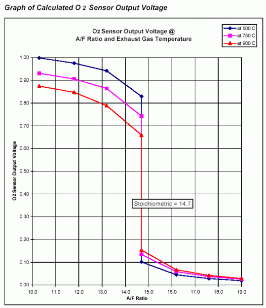
Narrowband oxygen sensor voltage output. The output is heavily dependent on sensor temperature and highly non-linear, making these sensors unsuitable for delivering a true AFR reading.
This generally involves putting in a wire jumper somewhere, attaching an LED, and watching it flash out the trouble codes. My Mazda was no exception, and after putting up with a car that was running rich enough to leave soot all over the rear bumper, I had to run the diagnostic.
It turned up three codes – one for the cam angle sensor, and two for the oxygen sensor. Now, a cam angle sensor (CAS) fault will normally prevent the car running at all, so it’s safe to assume that was an intermittent fault to keep an eye on.
The oxygen sensor, however, was clearly in need of attention. Its job is to allow the engine control unit (ECU) to monitor the fuel mixture in the exhaust, and make sure it’s not too rich or too lean. As my car was very obviously running too rich, and the diagnostic codes indicated an oxygen sensor failure, a repair was in order.
I priced up replacement sensors, and a new oxygen sensor could be had for under $100. However, it wasn’t exactly what I wanted, as not all oxygen sensors are created equal. Cars in the 80s and 90s typically shipped from the OEM fitted with what’s called a narrowband oxygen sensor. These almost always consist of a zirconia dioxide cell that outputs a voltage depending on the difference in oxygen concentration between the exhaust gas and the free air. These sensors generally sit at 0.45 V when the fuel mixture is stoichiometric, but rapidly change to 0.1 V in a lean condition and 0.9 V in a rich condition. The response is highly non-linear, and changes greatly with respect to temperature, and thus is only good for telling the ECU if it’s rich or lean, but not by how much. ECUs with narrowband sensors tend to hunt a lot when running in closed loop O2 control – you’ll see an engine at idle hunt either side of the magical 14.7 stoichiometric air fuel ratio, never able to quite dial in on the correct number.
As I intend to switch to an aftermarket ECU in the future, I’ll need to tune the car. This involves making sure the air/fuel ratios (AFRs) are correct, and for that I need to be able to properly measure them. Just knowing whether you’re rich or lean isn’t enough, as often it’s desirable to run the engine intentionally rich or lean at certain engine loads. To get a true AFR reading requires fitting a wideband oxygen sensor. These are a little more complicated.
Our Call for Proposals for the Hackaday Superconference was scheduled to close yesterday. We are extending that deadline by one week so get your proposal for a talk or a workshop in now.
We want to leave no stone unturned and are intimately familiar with the procrastination habits of busy hackers like you. Now there is no excuse. Put together your pitch now and send it our way. This is the ultimate hardware conference and we’re topics covering Engineering Heroics (how you managed to pull it together to get across the finish line), Prototyping, Research (building custom rigs for University/private industry/giggles), Product Development, Full-Stack Fabrication, and anything else you think fits the vibe of Hackaday.
Accepted talks receive free admission and access to speaker events. There are travel stipends available for exemplary proposals. We also record talks for publication after the Superconference so this is a chance to be famous on Hackaday.
The Hackaday SuperConference is November 11-12, 2017 in Pasadena California. There are still tickets available but what remains will sell out quickly when the slate of speakers in announced. Don’t miss out, grab your ticket now.
There are trends in YouTube videos among various video producers. A few weeks ago, it was all about fidget spinners until some niche tech blog ran that meme into the ground. Before that, the theme was red-hot knives cutting through stuff. The setup was simple; just heat a knife up with a blowtorch, cut through a tomato or golf ball, hit stop on the high-speed camera, and collect that sweet, sweet YouTube money.
[David] from RCExplorer.se isn’t like most YouTube stars. He actually knows what he’s doing. When the latest trend of rocket-propelled knives hit the tubes, he knew he could blow this out of the water. He succeeded with a fantastic rocket-propelled machete able to slice through watermelons and fling itself into the woods behind [David]’s house.
Unlike most of the other YouTube stars trying their hand at rocket-powered slicers, [David] is doing this one right. He’s using hobby rocket motors, yes, but they’re reloadable. [David] crafted an engine casing complete with a proper nozzle machined out of stainless for this build. The rocket sled itself is an aluminum bracket bolted to a piece of carbon fiber plate that travels down a rail with the help of four skateboard wheels. A machete is then bolted to the plate, which is propelled down the track a bit faster than 200 km/h.
When it comes to rocket-propelled knives, the word ‘professional’ really doesn’t come into play. This, however, is an amazing piece of craftsmanship that you can check out in the videos below.
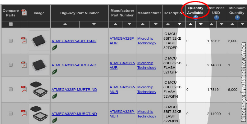
You’ve spent months developing your product, your Kickstarter just finished successfully, and now you’re ready to order all the parts. Unfortunately, your main component, an ATmega328P, is out of stock everywhere with a manufacturer lead time of 16 weeks. Now what?
When manufacturing things in large volumes, acquiring enough stock at the right time can be tricky. There can be seasonal shortages with companies trying to get products manufactured and available for Christmas. There can be natural disasters like floods of hard drive factories, or politically-related availability problems like tantalum for capacitors, or maybe new markets open up that increase demand or a new product sucks up all the available supply. The result is all the same; you have a harder time getting what you need. Fortunately, there are some ways to avoid this problem, or at least mitigate it.

 Sure, electric foundries lack some of the sex-appeal of gas- or even charcoal-fueled foundries, but by eschewing the open flames and shooting sparks, [Turbo Conquering Mega Eagle] was able to integrate the crucible into the foundry body and create what looks for all the world like a Thermos bottle for molten aluminum.