We’d Like, Totally Carry This Retro Boombox Cyberdeck On Our Shoulder

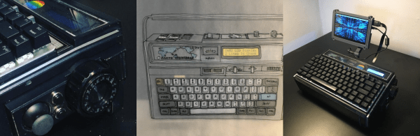
Cyberdeck. For those of a certain age, the ‘deck’ part conjures visions of tape decks, be they cassette, 8-track, or quarter-inch, and we seriously have to wonder why haven’t seen this type of build before. But here we are, thanks to [bongoplayingmonkey]’s Sanyo Cyberdeck, a truly retro machine built into a cool old boombox.

According to [bongoplayingmonkey], this was a unicorn of a build wherein everything more or less came together, soup to nuts. Right now, [bongoplayingmonkey] is cracking the nuts of a few remaining issues, like calibrating the analog VU meter that inspired the build in the first place. The plan is to use that to indicate various analog things such as battery power and the WiFi signal.

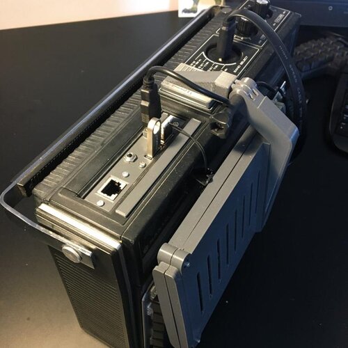
Luckily, everything survived the teardown, parts-wise. That huge knob has a new life has a rotary encoder for scrolling and middle click. And the VU meter made it too, thank Zod. This baby has full mouse controls thanks to a PS/2 joystick and a pair of vintage momentary buttons are likely chrome and bakelite to round out the look.

So apparently [bongoplayingmonkey]’s personal jury is still out on whether this is a blasphemous build or a divine ‘deck, but we say one thing is for sure: this is definitely art.

Unfortunately, the cassette deck didn’t survive. Otherwise, we might have to question its categorization — is it still a boombox if the tape deck works? This, however, is definitely a laptop that grew up to be a cyberdeck.

Thanks for the tip, [Blasto]!

Dynamicland Makes The Whole Building The Computer

Every once is a while a research project comes along that has the potential to totally shake up computing and what it even means to interact with a system. The project Dynamicland.org, is a result of [Bret Victor]’s research journey over the years, looking into various aspects of human computer interaction and what it even means to think like a human.

One of the overhead projectors tied to a realbox
In Realtalk, paper is your programming medium

Dynamicland is an instantiation of a Realtalk ecosystem, deployed into a whole building. Tables are used as computing surfaces, with physical objects such as pieces of paper, notebooks, anything which can be read by one of the overhead cameras, becoming the program listing, as well as the user interface. The camera is associated with a projector, with the actual hardware hooked into so-called ‘Realboxes’ which are Linux machines running the Realtalk software. Separate Realboxes (and other hardware such as a Raspberry Pi, running Realtalk) are all federated together using the Realtalk protocol, which allows communication from hardware in the ceiling, to any on the desk, and also to other desks and computing surfaces.

Realtalk itself is described as an environment for authoring and using computation media. The Realtalk system provides a language extension to Lua. Together these form a domain-specific language. Realtalk is also a kind of reactive database, which means that the emphasis is on the flow of data and connections between data producing things, and data consuming things. For a bit more explanation of how reactive programming can be used with modern relational databases, check out this article on the subject.

For a good overview of how this works in practice, from a programming perspective, checkout [Omar Rizwan]’s article about his ‘Geokit’ project. Another interesting read is the work by [Andrés Cuervo.]

Continue reading “Dynamicland Makes The Whole Building The Computer”

Line Following Robot Uses PID For Speed

While a line-following robot may not be the newest project idea in the book, this one from [Edison Science] is a clean build using modern components and gets a good speed thanks to PID control feedback instead of the more traditional bang-bang control you see in low-end robots.

Of course, PIDs need tuning and that seems to be the weak link — you’ll have to experiment with the settings. The sensors also require calibration, but we bet both of those issues could be fixed pretty easily.

Continue reading “Line Following Robot Uses PID For Speed”

Cast-in-Concrete Clock Upgraded After Thirteen Years

Proving that an old design cast in concrete can indeed be changed, [Hans Jørgen Grimstad] has revisited his Nixie clock from 2008, cleaned up the electronics and packaging, and turned it into a kit. Not that he has plans to enter the kit-making business, but he just thought it would be fun to learn how to make kits. In the video below the break, he’s a bit embarrassed to reveal the inside of his first Nixie clock design, housed in a cast-concrete electronics enclosure. Although it still works, the internal wiring is a flaky, untidy, and perhaps a bit dangerous.

But [Hans] has improved his game over the years, making a number of different clock designs. The latest incarnation is pleasant to look at, built on a PCB which is visible inside a custom acrylic case. Three versions are available to support different types of tubes. The documentation he prepared for the project and the kit is very thorough. He walks you through the unboxing and assembly process in the videos below. Firmware is in C, and runs on a Raspberry Pi Zero W. If you are interesting in making electronics kits, [Hans]’s project would be a good example to follow.

All the necessary information to build the clock is published on the project’s GitHub repository. If you’re looking for enclosure ideas other than concrete or acrylic sheet, check out this write-up on hand-forging artistic Nixie clock enclosures.

Continue reading “Cast-in-Concrete Clock Upgraded After Thirteen Years”

Solar Powered Autonomous Tugboat For Rescuing Autonomous Vessels

[rctestflight] has built several autonomous boats, and with missions becoming longer and more challenging, he bought an inflatable kayak to serve as a dedicated rescue vessel. Instead of relying on outdated manual paddling, he built an autonomous solar-powered tugboat.

Towing test with kayak
♪ “Rum, treasure, ArduRover, Pixhawk 4 and so much solar, break of dawn till the day is over, the ship will surely go…” ♪

The tugboat uses a pair of molded fiberglass hulls in a catamaran configuration. The wide platform allows a pair of 100W solar panels to be mounted on top. It was [rctestflight]’s first time molding anything out of fiberglass, so there was quite a bit of trial and error going on. The mold was 3D printed in sections, aligned with dowel pins, and glued together. After the epoxy had cured, the mold halves could be split apart for easier removal of the hull.

As with most of [rctestflights] autonomous vehicles, control is handled by a Pixhawk 4 running ArduPilot/ArduRover. A pair of 76 mm brass propellers powered by brushless motors provide propulsion and differential steering. The motors get power from six LiFePO4 batteries, which charge from the solar panels via MPPT charge controllers. The hulls are covered with plywood decks with removable hatches and inspection windows. After a bit of tuning, he took the boat for a few test runs, the longest being 5.1 km with himself in tow in the kayak. At less than 5 km/h (3 mph) it’s no speedboat, but certainly looks like a relaxing ride. Many of [rctestflight]’s previous vessels were airboats to avoid getting underwater propellers tangled in weeds. It was less of an issue this time since he could just haul the tugboat close to the kayak and clear the propellers.

[rctestflights] are always entertaining and educational to watch, and this one certainly sets the standard for sea-shanty soundtracks at 13:32 in part two.

Continue reading “Solar Powered Autonomous Tugboat For Rescuing Autonomous Vessels”

Finding The Right Hack Is Half The Battle

Sometimes you just get lucky. I had a project on my list for a long time, and it was one that I had been putting off for a few months now because I loathed one part of what it entailed — sensitive, high-accuracy analog measurement. And then, out of the blue I stumbled on exactly the right trick, and my problems vanished in thin air. Thanks, Internet of Hackers!

The project in question is a low-vacuum regulator for “bagging” fiberglass layups. What I needed was some way to read a pressure sensor and turn on and off a vacuum pump accordingly. The industry-standard vacuum gauges are neat devices, essentially a tiny little strain gauge on a membrane between the vacuum side and the atmosphere side, in a package the size of a dime. (That it’s a strain gauge is foreshadowing, but I didn’t know that at the time.) I bought one for $15 ages ago, and it sat on my desk, awaiting its analog circuitry.

See, the MPX2100 runs on 12 V and puts out a signal around 40 mV on top of a 6 V offset. That voltage level is inconvenient for modern 3.3 V microcontroller ADCs, and the resolution would get clobbered by the 6 V signal if I just put a voltage divider on it. This meant whipping together some kind of instrument amplifier circuit to null out the 6 V and amplify the 40 mV for the ADC. The circuits I found online all called for 1% resistors in values I didn’t have, and mildly special op-amps. No fun, for me at least. So there it sat.

Picture of sketchy-looking vacuum apparatus.
Cut the blue wire or the red wire? HX711 module and pressure sensor on the left.

Until I ran into this project that machetes through the analog jungle with one part, and it happened to be one I had on hand. A vacuum pressure sensor is a strain gauge, set up like a Wheatstone bridge, just like you would use for weighing something with a load cell. The solution? A load-cell ADC chip, the HX711, found in every cheap scale or online for under a buck. The only other trick was finding a low-voltage pressure sensor to work with it, but that turns out to be easy as well, and I had one delivered in two days.

In all, this project took months of foot-dragging, but only a few clicks and five minutes of soldering once I got the right idea. The industrial applications and manufacturers’ app notes all make sense if you are making hundreds or millions of these devices, where the one-time cost of prototyping up the hard bits gets amortized, but the hacker solution of using a weight-scale chip was just the ticket for a one-off. That just goes to show how useful sharing our tips and tricks can be — you won’t get this from the industry. So send us your success stories, and your useful failures too, and Read More Hackaday!

SLA printer rigged for time lapse

Silky Smooth Resin Printer Timelapses Thanks To Machine Vision

The fascination of watching a 3D printer go through its paces does tend to wear off after you spent a few hours doing it, in which case those cool time-lapse videos come in handy. Trouble is they tend to look choppy and unpleasant unless the exposures are synchronized to the motion of the gantry. That’s easy enough to do on FDM printers, but resin printers are another thing altogether.

Or are they? [Alex] found a way to make gorgeous time-lapse videos of resin printers that have to be seen to be believed. The advantage of his method is that it’ll work with any camera and requires no hardware other than a little LED throwie attached to the build platform of the printer. The LED acts as a fiducial that OpenCV can easily find in each frame, one that indicates the Z-axis position of the stage when the photo was taken. A Python program then sorts the frames, so it looks like the resin print is being pulled out of the vat in one smooth pull.

To smooth things out further, [Alex] also used frame interpolation to fill in the gaps where the build platform appears to jump between frames using real-time intermediate flow estimation, or RIFE. The details of that technique alone were worth the price of admission, and the results are spectacular. Alex kindly provides his code if you want to give this a whack; it’s almost worth buying a resin printer just to try.

Is there a resin printer in your future? If so, you might want to look over [Donald Papp]’s guide to the pros and cons of SLA compared to FDM printers.

Continue reading “Silky Smooth Resin Printer Timelapses Thanks To Machine Vision”