Hackaday Podcast 107: FTDI Plays Music, LED Dimming Ain’t Easy, Measuring Poop Calories, And Sketchy Laser Cutters

Hackaday editors Mike Szczys and Elliot Williams gab about all of the geeky things. We had a delightful time watching NASA bring Perseverance down to the Red planet. In Kristina’s words, we pour one out for Fry’s Electronics. And then we jump into a parade of excellent hacks with a magnetic bearing for crooked ball screws, a science-based poop-burning experiment, and the music hack only microcontroller enthusiasts could love as an FTDI cable is plugged directly into a speaker. Smart circuit design is used to hack a dimmer into non-dimmable LED fixtures, and an octet of living clams are the early warning sensors for water pollution.

Take a look at the links below if you want to follow along, and as always, tell us what you think about this episode in the comments!

Direct download (~60 MB)

Places to follow Hackaday podcasts:

Continue reading “Hackaday Podcast 107: FTDI Plays Music, LED Dimming Ain’t Easy, Measuring Poop Calories, And Sketchy Laser Cutters”

Audio Out Over A UART With An FTDI USB-To-TRS Cable

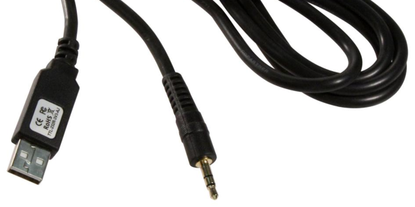
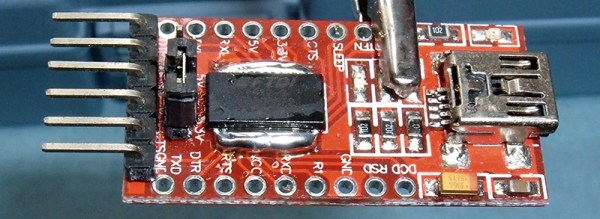
What is the easiest way to get audio from a WAV file into a line-level format, ready to be plugged into the amplifier of a HiFi audio set (or portable speaker)? As [Konrad Beckmann] demonstrated on Twitter, all you really need is a UART, a cable and a TRS phono plug. In this case a USB-TTL adapter based around the FTDI FT232R IC: the TTL-232R-3V3-AJ adapter with 12 Mbps USB on one end, and a 3 Mbps UART on the other end.

[Konrad] has made the C-based code available on GitHub. Essentially what happens underneath the hood is that it takes in a PCM-encoded file (e.g. WAV). As a demonstration project, it requires the input PCM files to be a specific sample rate, as listed in the README, which matches the samples to the baud rate of the UART. After this it’s a matter of encoding the audio file, and compiling the uart-sound binary.

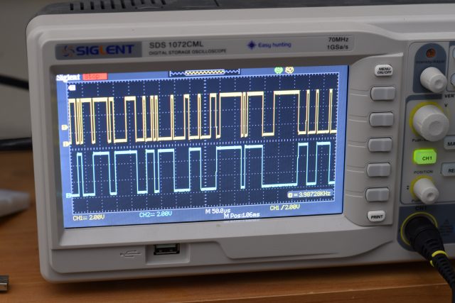
The output file is the raw audio data, which is encoded in PDM, or Pulse-Density Modulation. Unlike Pulse-Code Modulation (PCM), this encoding method does not encode the absolute sample value, but uses binary pulses, the density of which corresponds to the signal level. By sending PDM data down the UART’s TX line, the other side will receive these bits. If said receiving device happens to be an audio receiver with an ADC, it will happily receive and play back the PDM signal as audio. As one can hear in the video embedded in the tweet, the end result is pretty good.


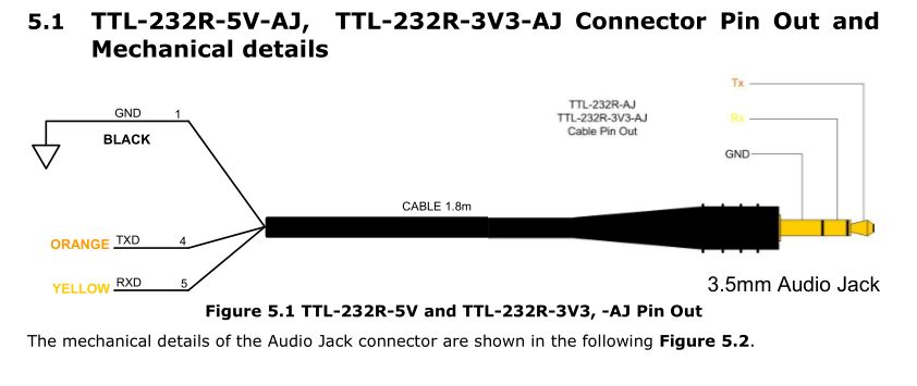
If we look at at the datasheet for the TTL-232R-3V3-AJ adapter cable, we can see how it is wired up:

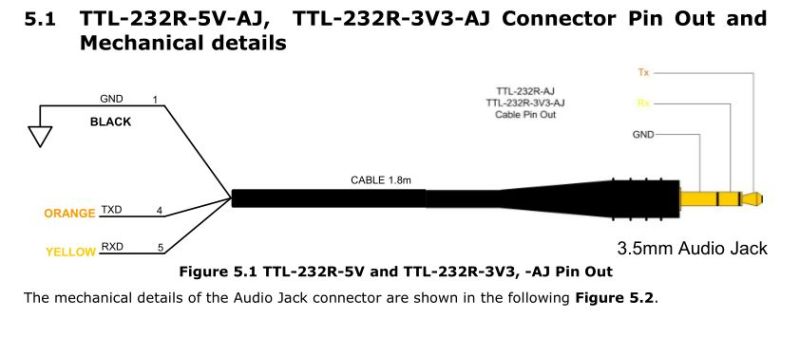
When we compare this to the wiring of a standard audio TRS jack, we can see that the grounds match in both wirings, and TX (RX on the receiving device) would match up with the left channel, with the right channel unused. A note of caution here is also required: this is the 3.3V adapter version, and it lists its typical output high voltage as 2.8V, which is within tolerances for line-level inputs. Not all inputs will be equally tolerant of higher voltages, however.

Plugging random TRS-equipped devices into one’s HiFi set, phone or boombox is best done only after ascertaining that no damage is likely to result.  Be safe, and enjoy the music.

FTDI VCP Chips With Custom PIDs Not Working On MacOS 11 Big Sur

An anonymous reader pinged us about an issue that affects people who jumped onto the latest-and-greatest OS from the Apple gardens: USB devices that stop working due to the FTDI-based USB solution. At its core appears to be that the built-in FTDI driver provided by Apple (AppleUSBFTDI.dext) only supports FTDI chips which provide the standard FTDI vendor and product ID (e.g. 0x0403 and 0x6001 respectively for the FT232R). Many products however set a custom product ID (PID) to differentiate their device, though in the thread some mention that there are driver issues even with the default VID/PID combination.

Over the past years, Apple has been restricting and changing the way kernel extensions (KExt) and driver extensions (DExt) are handled. As these FTDI chips are often used for virtual com port (VCP) purposes, such as with Arduino boards and USB-TTL adapters, this is a rather cumbersome issue that would affect anyone using Big Sur in combination with such a hardware device.

So far only the FTDI team has been somewhat responsive based on the support forum thread, with Apple seemingly rather silent on the issue.

Using FTDI Chips With Python

FTDI are a company known for producing chips for USB applications. Most of us have a few USB-to serial adapters kicking about, and the vast majority of them run on FTDI hardware (or, if we’re honest, counterfeit copies). However, FTDI’s hardware has a whole lot more to offer, and [jayben] is here to show us all how to take advantage of it using Python.

FTDI chips are an effective way to debug ARM projects, using the SWD protocol.

FTDI’s chips have varying capabilities, but most can do more than just acting as a USB-connected COM port. It’s possible to use the chips for SPI, I2C, or even bitbanging operation. [jayben] has done the hard work of identifying the best drivers to use depending on your operating system, and then gone a step further to demonstrate example code for sending data over these various interfaces. The article not only covers code, but also shows oscilloscope traces of output, giving readers a strong understanding of what should be happening if everything’s operating as it should. The series rounds out with a primer on how to use FTDI hardware to speak the SWD protocol to ARM devices for advanced debugging use.

It’s a great primer on how to work effectively with these useful chips, and we imagine there will be plenty of hackers out there that will find great use to this information. Of course, it’s important to always be careful when sourcing your hardware as FTDI drivers don’t take kindly to fake chips.

Silicon Bugs In The FTDI FT232R, And A Tidy RF VCO Project

[Scott Harden] wrote in to tell us of some success he’s having using the FT232 chip to speak SPI directly from his laptop to a AD98850 digital signal generator. At least that was his destination. But as so often in life, more than half the fun was getting there, finding some still-unsolved silicon bugs, and (after simply swapping chips for one that works) potting it with hot glue, putting it in a nice box, and putting it up on the shelf.

In principle, the FTDI FT232 series of chips has a bit-bang mode that allows you to control the individual pins from a fairly simple API on your target computer, using their drivers and without installing anything on basically any platform. We wrote this feature up way back in 2009, and [Scott] was asking himself why he doesn’t see more hacks taking advantage of bit-bang mode.

“Square” waves

Then he answered his own question the hard way, by spending hours “debugging” his code until he stumbled on the FTDI errata note (PDF), where they admit that bit-bang mode doesn’t get timings right at all on the FT232R and FT232RL parts. FTDI has made claims that they fixed the bug in subsequent chip revisions, but the community has not been able to confirm it. If you want to use bit-bang mode, which is plenty cool, steer clear of the FT232R chips — the ones found in the ever-popular FTDI cables and many adapter dongles.

The good news here is twofold. First, now you know. Second, bit-bang mode is tremendously useful and it works with other chips from the vendor. Particularly, the FT232H and FT230X chips work just fine, among others. And [Scott] got his command-line controlled digital VCO up and running. All’s well that ends well?

We’ll wrap up with questions for the comment section. Do other manufacturers’ cheap USB-serial chips have an easily accessible bit-bang mode? Are any of you using USB bit-bang anyway? If so, what for?

Fixing Fake FTDIs

If you know where to go on the Internet, you can pick up an FTDI USB to Serial adapter for one dollar and sixty-seven cents, with free shipping worldwide. The chip on this board is an FTDI FT232RL, and costs about two dollars in quantity. This means the chips on the cheap adapters are counterfeit. While you can buy a USB to serial adapter with a legitimate chip, [Syonyk] found a cheaper solution: buy the counterfeit adapters, a few genuine chips, and rework the PCB. It’s brilliant, and an excellent display of desoldering prowess.

Why is [Syonyk] replacing non-genuine chips with the real FTDI? The best reason is FTDIgate Mk. 1, where the official FTDI driver for Windows detected non-genuine chips and set the USB PID to zero. This bricked a whole bunch of devices, and was generally regarded as a bad move. FTDIgate Mk. 2 was a variation on a theme where the FTDI driver would inject garbage data into a circuit if a non-genuine part was found. This could also brick devices. Notwithstanding driver issues, the best reason for swapping out fake chips for real ones is the performance at higher bit rates; [Syonyk] is doing work at 3 Mbps, and the fake chips just don’t work that fast.

To replace the counterfeit chip, [Syonyk] covered the pins in a nice big glob of solder, carefully heated both sides of the chip, and slid the offending chip off when everything was molten. A bit of solder braid, and the board was ready for the genuine chip.

With the new chip, the cheap USB to serial adapter board works perfectly, although anyone attempting to duplicate these efforts might want to look into replacing the USB mini port with a USB micro port.

Adafruit Interviews The CEO Of FTDI

When it comes to electronic hobbyists and EEs, there is no company that deserves a few raised eyebrows than FTDI. They made their name with USB converter chips, namely USB to serial chips that are still very popular today. So popular, in fact, that clones of these chips are frequently found in the $2 Arduinos from China, and other very low-cost devices. A little more than a year ago, a few clever people noticed FTDI drivers were bricking these counterfeit chips by setting the USB PID to 0000. The Internet reacted to this move and FTDI quickly backed down from that position. The Windows driver was fixed, for about a year until the same shenanigans were found again.

Adafruit recently sat down with [Fred Dart], CEO of FTDI, giving us all the first facts and figures that aren’t from people frustrated with Windows’ automatically updated drivers. The most interesting information from [Fred Dart] is how FTDI first found these counterfeit chips, what FTDI chips are being counterfeited, and how many different companies are copying these chips.

The company first realized they were being cloned when they couldn’t reproduce results of a Chinese-made ‘FTDI’ USB to RS232 cable that behaved strangely. A sample of the cables were shipped to FTDI and after inspecting the chip inside, FTDI found it was a clone with a significantly different architecture than a genuine chip.

So far, the counterfeiters appear to only be counterfeiting the SSOP version of the FT232RL and occasionally the older FT232BL chip. From what FTDI has seen, there appears to be only one or two companies counterfeiting chips.

As the CEO of FTDI, [Fred] has a few insights into what can be done to stop counterfeiters in China. The most important is to trademark the logo. This isn’t just the logo for a webpage, but one that can be laser etched onto the plastic package of the chip. US Customs has been very amenable to identifying counterfeit components, and this has led to several shipments being destroyed. Legal action, however, is a bit hard in China, and FTDI is dealing with a gang that counterfeits more than FTDI chips; there’s a high likelihood this gang was responsible for the fake Prolific PL23o3 chips a few years ago.

As far as FTDI bricking counterfeit chips is concerned, [Fred Dart] wasn’t silent on the issue, he merely wasn’t asked the question and didn’t bring it up himself.