The green CRT display of a scanning-electron microscope is shown, displaying small particles.

DIY Calibration Target For Electron Microscopes

It’s a problem that few of us will ever face, but if you ever have to calibrate your scanning electron microscope, you’ll need a resolution target with a high contrast under an electron beam. This requires an extremely small pattern of alternating high and low-density materials, which [ProjectsInFlight] created in his latest video by depositing gold nanoparticles on a silicon slide.

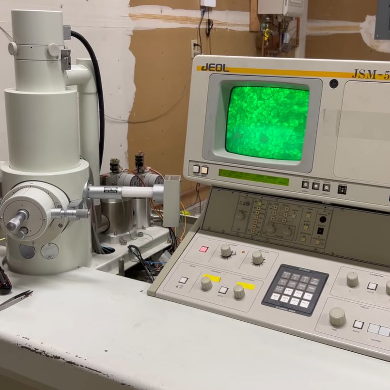
[ProjectsInFlight]’s scanning electron microscope came from a lab that discarded it as nonfunctional, and as we’ve seen before, he’s since been getting it back into working condition. When it was new, it could magnify 200,000 times and resolve features of 5.5 nm, and a resolution target with a range of feature sizes would indicate how high a magnification the microscope could still reach. [ProjectsInFlight] could also use the target to make before-and-after comparisons for his repairs, and to properly adjust the electron beam.

Since it’s easy to get very flat silicon wafers, [ProjectsInFlight] settled on these as the low-density portion of the target, and deposited a range of sizes of gold nanoparticles onto them as the high-density portion. To make the nanoparticles, he started by dissolving a small sample of gold in aqua regia to make chloroauric acid, then reduced this back to gold nanoparticles using sodium citrate. This gave particles in the 50-100 nanometer range, but [ProjectsInFlight] also needed some larger particles. This proved troublesome for a while, until he learned that he needed to cool the reaction temperature solution to near freezing before making the nanoparticles.

Using these particles, [ProjectsInFlight] was able to tune the astigmatism settings on the microscope’s electron beam so that it could clearly resolve the larger particles, and just barely see the smaller particles – quite an achievement considering that they’re under 100 nanometers across!

Electron microscopes are still a pretty rare build, but not unheard-of. If you ever find one that’s broken, it could be a worthwhile investment.

Continue reading “DIY Calibration Target For Electron Microscopes”

Building The Simplest Atomic Force Microscope

Doing it yourself may not get you the most precise lab equipment in the world, but it gets you a hands-on appreciation of the techniques that just can’t be beat. Today’s example of this adage: [Stoppi] built an atomic force microscope out of mostly junk parts and got pretty good results, considering. (Original is in German; read it translated here.)

The traditional AFM setup uses a piezo micromotor to raise and lower the sample into a very, very fine point. When this point deflects, it reads the height from the piezo setup and a motor stage moves on to the next point. Resolution is essentially limited by how fine a point you can make and how precisely you can read from the motion stages. Here, [stoppi]’s motion stage follows the traditional hacker avenue of twin DVD sleds, but instead of a piezo motor, he bounces a laser off of a mirror on top of the point and reads the deflection with a line sensor. It’s a clever and much simpler solution.

A lot of the learnings here are in the machine build. Custom nichrome and tungsten tips are abandoned in favor of a presumably steel compass tip. The first-draft spring ended up wobbling in the X and Y directions, rather than just moving in the desired Z, so that mechanism got reinforced with aluminum blocks. And finally, the line sensors were easily swamped by the laser’s brightness, so neutral density filters were added to the project.

The result? A nice side effect of the laser-bouncing-off-of-mirror setup is that the minimum resolvable height can be increased simply by moving the line sensors further and further away from the sample, multiplying the deflection by the baseline. Across his kitchen, [stoppi] is easily able to resolve the 35-um height of a PCB’s copper pour. Not bad for junk bin parts, a point from a crafts store, and a line sensor.

If you want to know how far you can push a home AFM microscope project, check out [Dan Berard]’s absolutely classic hack. And once you have microscope images of every individual atom in the house, you’ll, of course, want to print them out.

Make Your Cheap Thermal Camera Into A Microscope

[Project 326] has a cheap thermal camera that plugs into a smart phone. Sure they are handy, but what if you could hack one into a microscope with a resolution measured in microns? It is easier than you might think and you can see how in the video below.

Of course, microscopes need lenses, but glass doesn’t usually pass IR very well. This calls for lenses made of exotic material like germanium. One germanium lens gives some magnification. However, using a 3D printed holder, three lenses are in play, and the results are impressive.

The resolution is good enough to see the turns of wire in an incandescent light bulb. A decapsulated power transistor was interesting to view, too. Imaging heat at that much resolution gives you a lot of information. At the end, he teases that using first surface mirrors, he may show how to build an IR telescope as well.

Presumably, this will work with just about any IR camera if you adapt the lens holder. The unit in the video is a UNI-T UTi-260M. So when he says he spent about $35 on the build, that’s not including the $400 or so camera module.

IR imaging can pull off some amazing tricks, like looking inside an IC. If the thermal camera used in the video isn’t to your liking, there are plenty of others out there.

Continue reading “Make Your Cheap Thermal Camera Into A Microscope”

Homebrew Electron Beam Lithography With A Scanning Electron Microscope

If you want to build semiconductors at home, it seems like the best place to start might be to find a used scanning electron microscope on eBay. At least that’s how [Peter Bosch] kicked off his electron beam lithography project, and we have to say the results are pretty impressive.

Now, most of the DIY semiconductor efforts we’ve seen start with photolithography, where a pattern is optically projected onto a substrate coated with a photopolymer resist layer so that features can be etched into the surface using various chemical treatments. [Peter]’s method is similar, but with important differences. First, for a resist he chose poly-methyl methacrylate (PMMA), also known as acrylic, dissolved in anisole, an organic substance commonly used in the fragrance industry. The resist solution was spin-coated into a test substrate of aluminized Mylar before going into the chamber of the SEM.

As for the microscope itself, that required a few special modifications of its own. Rather than rastering the beam across his sample and using a pattern mask, [Peter] wanted to draw the pattern onto the resist-covered substrate directly. This required an external deflection modification to the SEM, which we’d love to hear more about. Also, the SEM didn’t support beam blanking, meaning the electron beam would be turned on even while moving across areas that weren’t to be exposed. To get around this, [Peter] slowed down the beam’s movements while exposing areas in the pattern, and sped it up while transitioning to the next feature. It’s a pretty clever hack, and after development and etching with a cocktail of acids, the results were pretty spectacular. Check it out in the video below.

It’s pretty clear that this is all preliminary work, and that there’s much more to come before [Peter] starts etching silicon. He says he’s currently working on a thermal evaporator to deposit thin films, which we’re keen to see. We’ve seen a few sputtering rigs for thin film deposition before, but there are chemical ways to do it, too.

Continue reading “Homebrew Electron Beam Lithography With A Scanning Electron Microscope”

Saving An Electron Microscope From The Trash

Who wouldn’t want to have a scanning electron microscope (SEM)? If you’re the person behind the ProjectsInFlight channel on YouTube, you certainly do. In a recent video it’s explained how he got his mittens on a late 1980s, early 1990s era JEOL JSM-5200 SEM that was going to be scrapped. This absolute unit of a system comes with everything that’s needed to do the imaging, processing and displaying on the small CRT. The only problem with it was that it was defective, deemed irreparable and hence the reason why it was headed to the scrap. Could it still be revived against all odds?

The JEOL JSM-5200 SEM after being revived and happily scanning away. (Credit: ProjectsInFlight, YouTube)

The good news was that the unit came with the manual and schematics, and it turns out there’s an online SEM community of enthusiasts who are more than happy to help each other out. One of these even had his own JSM-5200 which helped with comparing the two units when something wasn’t working. Being an SEM, the sample has to be placed in a high vacuum, which takes a diffusion vacuum pump, which itself requires a second vacuum pump, all of which requires voltages and electronics before even getting to the amplification circuitry.

Since the first problem was that this salvaged unit wasn’t turning on, it started with the power supply and a blown fuse. This led to a shorted transformer, bad DC-DC converters, a broken vacuum pump, expired rubber hoses and seals, and so on, much of which can be attributed simply to the age of the machine. Finding direct replacements was often simply impossible to very expensive, necessitating creative solutions along with significant TLC.

Although there are still some small issues with for example the CRT due to possibly bad capacitors, overall the SEM seems to be in working condition now, which is amazing for a unit that was going to be trashed.

Thanks to [Hans] for the tip.

Continue reading “Saving An Electron Microscope From The Trash”

Hackaday Podcast Episode 291: Walking In Space, Lead In The Earth, And Atoms Under The DIY Microscope

What have you missed on Hackaday this week? Elliot Williams and Al Williams compare notes on their favorites from the week, and you are invited. The guys may have said too much about the Supercon badge this year — listen in for a few hints about what it will be about.

For hacks, you’ll hear about scanning tunneling microscopes, power management for small Linux systems, and lots of inertial measurement units. The guys talked about a few impossible hacks for consumer electronics, from hacking a laptop, to custom cell phones.

Of course, there are plenty more long-form articles of the week, including a brief history of what can go wrong on a spacewalk and how to get the lead out (of the ground). Don’t forget to take a stab at the What’s That Sound competition and maybe score a sweet Hackaday Podcast T-shirt.

Check out the links below if you want to follow along, and as always, tell us what you think about this episode in the comments!

Use this link to teleport a DRM-free MP3 to your location.

Continue reading “Hackaday Podcast Episode 291: Walking In Space, Lead In The Earth, And Atoms Under The DIY Microscope”

Building A 3D Printed Scanning Tunneling Microscope

YouTuber [MechnicalRedPanda] has recreated a DIY STM hack we covered about ten years ago, updating it to be primarily 3D-printed, using modern electronics, making it much more accessible to many folks. This simple STM setup utilises a piezoelectric actuator constructed by deliberately cutting a piezo speaker into four quadrants. With individual drive wires attached to the four quadrants. [MechPanda] (re)discovered that piezoelectric ceramic materials are not big fans of soldering heat. Still, in the absence of ultrasonic welding equipment, he did manage to get some wires to take to the surface using low-temperature solder paste.

As you can tell, you can only image conductive samples

A makeshift probe holder was glued on the rear side of the speaker actuator, which was intended to take a super sharp needle-like piece of tungsten wire. Putting the wire in tension and cutting at a sharp angle makes it possible with many attempts to get some usable points. Usable, in this instance, means sharp down the atomic level. The sample platform, actuator mount and all the connecting parts are 3D-printed with PA-CF. This is necessary to achieve enough mechanical stability with normal room temperature fluctuations. Three precision screws are used to level the two platforms in a typical kinematic mount structure, which looks like the only hard-to-source component. A geared stepper motor attached to the probe platform is set up to allow the probe to be carefully advanced towards the sample surface. Continue reading “Building A 3D Printed Scanning Tunneling Microscope”