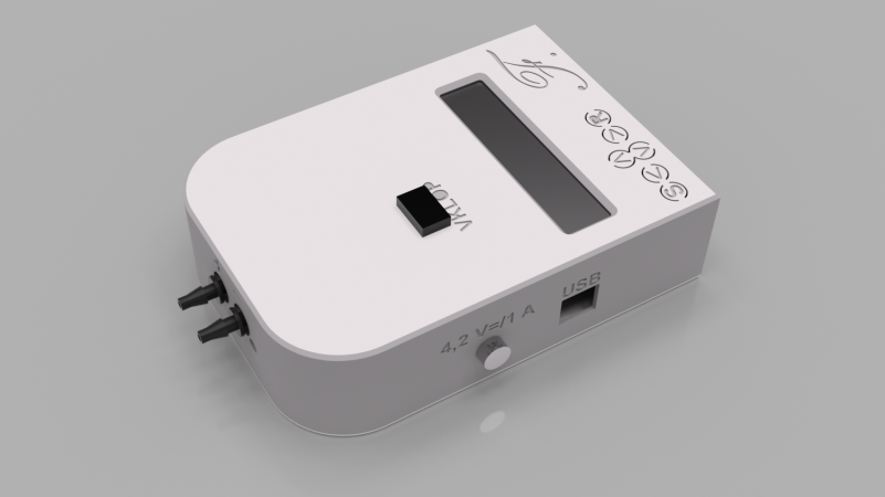
When we hear about flash drives in the context of cybersecurity, we tend to think of them more as threats than as targets. When you’re using flash drives to store encryption keys, however, it makes sense to pay more attention to their security. [Juergen] designed the PECKUS (Presence Enforcing Crypto-Key USB-Storage) with this specifically in mind: a few-kilobyte storage device that only unlocks if the owner’s Bluetooth device is in the vicinity.
[Juergen] needed to store an infrequently-used keyfile on an air-gapped system, and commercial encrypted flash drives were rather expensive and left much to be desired in terms of usability. Instead, he designed a CircuitPython custom firmware for MakerDiary’s nRF52840 micro development kit, which provided a BLE-capable system in the form of a USB dongle.
After flashing the firmware to the board, the user sets it up with a particular Bluetooth device and a file to be stored; after writing the file during setup, it cannot be rewritten. Before reading from the device, the user must pair the previously-set device with the board and press a button on the board, and only then does the device appear to the computer.
The limited amount of storage space means that this device will probably only serve its intended purpose, but in those cases, it’ll be handy to have an open-source and inexpensive protected storage device. [Juergen] notes that attackers could theoretically defeat this system by desoldering the microcontroller from the board and extracting the memory contents from the its storage, but if you have enemies that resourceful, you probably won’t be relying on a $20 board anyways.
We’ve previously seen a few flashdrives cross these pages, including one meant to self-destruct, and one made from a rejected microSD card.

Author: Aaron Beckendorf194 Articles
Using Pitot Tubes For More Than Aircraft
When we hear the words “pitot tube,” we tend to think more of airplanes than of air ducts, but [Franci Kopač]’s guide to pitot tubes for makers shows that they can be a remarkably versatile tool for measuring air speed, even in domestic settings.
A pitot tube is a tube which faces into an air flow, with one hole at the front of the tube, and one on the side. It’s then possible to determine the air speed by measuring the pressure difference between the side opening and the end facing into the wind. At speeds, temperatures, and altitudes that a hacker’s likely to encounter (i.e. not on an airplane), the pressure difference is pretty small, and it’s only since the advent of MEMS pressure sensors that pitot tubes became practical for amateurs.
[Franci]’s design is based on a Sensiron SDP differential pressure sensor, a 3D-printed pitot tube structure, some tubing, and the microcontroller of your choice. It’s important to position the tube well, so that it doesn’t experience airflow disturbances from other structures and faces straight into the air flow. Besides good positioning, the airspeed calculation requires you to know the air temperature and absolute pressure.
[Franci] also describes a more exotic averaging pitot tube, a fairly simple variation which measures air speed in cavities more accurately. He notes that this provides a more inexpensive way of measuring air flow in ducts than air conditioning flow sensors, while being more resilient than propeller-based solutions – he himself used pitot tubes to balance air flow in his home’s ventilation. All of the necessary CAD files and Arduino code are available on his GitHub repository.
If you’re looking for a more conventional duct flow meter, we’ve covered one before. We’ve even seen a teardown of a pitot tube sensor system from a military drone.
Designing A Hobbyist’s Semiconductor Dopant
[ProjectsInFlight] has been on a mission to make his own semiconductors for about a year now, and recently shared a major step toward that goal: homemade spin-on dopants. Doping semiconductors has traditionally been extremely expensive, requiring either ion-implantation equipment or specialized chemicals for thermal diffusion. [ProjectsInFlight] wanted to use thermal diffusion doping, but first had to formulate a cheaper dopant.
Thermal diffusion doping involves placing a source of dopant atoms (phosphorus or boron in this case) on top of the chip to be doped, heating the chip, and letting the dopant atoms diffuse into the silicon. [ProjectsInFlight] used spin-on glass doping, in which an even layer of precursor chemicals is spin-coated onto the chip. Upon heating, the precursors decompose to leave behind a protective film of glass containing the dopant atoms, which diffuse out of the glass and into the silicon.
After trying a few methods to create a glass layer, [ProjectsInFlight] settled on a composition based on tetraethyl orthosilicate, which we’ve seen used before to create synthetic opals. After finding this method, all he had to do was find the optimal reaction time, heating, pH, and reactant proportions. Several months of experimentation later, he had a working solution.
After some testing, he found that he could bring silicon wafers from their original light doping to heavy doping. This is particularly impressive when you consider that his dopant is about two orders of magnitude cheaper than similar commercial products.
Of course, after doping, you still need to remove the glass layer with an oxide etchant, which we’ve covered before. If you prefer working with lasers, we’ve also seen those used for doping. Continue reading “Designing A Hobbyist’s Semiconductor Dopant”
Magnetohydrodynamic Motors To Spin Satellites
Almost all satellites have some kind of thrusters aboard, but they tend to use them as little as possible to conserve chemical fuel. Reaction wheels are one way to make orientation adjustments without running the thrusters, and [Zachary Tong]’s liquid metal reaction wheel greatly simplifies the conventional design.
Reaction wheels are basically flywheels. When a spacecraft spins one, conservation of angular momentum means that the wheel applies an equal and opposite torque to the spacecraft, letting the spacecraft orient itself. The liquid-metal reaction wheel uses this same principle, but uses a loop of liquid metal instead of a wheel, and uses a magnetohydrodynamic drive to propel the metal around the loop.
[Zach] built two reaction wheels using Galinstan as their liquid metal, which avoided the toxicity of a more obvious liquid metal. Unfortunately, the oxide skin that Galinstan forms did make it harder to visualize the metal’s motion. He managed to get some good video, but a clearer test was their ability to produce torque. Both iterations produced a noticeable response when hung from a string and activated, and achieved somewhat better results when mounted on a 3D-printed air bearing.
Currently, efficiency is the main limitation of [Zach]’s motors: he estimates that the second model produced 6.2 milli-newton meters of torque, but at the cost of drawing 22 watts. The liquid metal is highly conductive, so the magnetohydrodynamic drive takes high current at low voltage, which is inconvenient for a spacecraft to supply. Nevertheless, considering how hard it is to create reliable, long-lasting reaction wheels the conventional way, the greatly improved resilience of liquid-metal reaction wheels might eventually be worthwhile.
If you’re curious for a deeper look at magnetohydrodynamic drives, we’ve covered them before. We’ve also seen [Zach]’s earlier experiments with Galinstan.
Continue reading “Magnetohydrodynamic Motors To Spin Satellites”
Home-casting Thermoelectric Alloys
If you want to convert heat into electrical power, it’s hard to find a simpler method than a thermoelectric generator. The Seebeck effect means that the junction of two dissimilar conductors will produce a voltage potential when heated, but the same effect also applies to certain alloys, even without a junction. [Simplifier] has been trying to find the best maker-friendly thermoelectric alloys, and recently shared the results of some extensive experimentation.
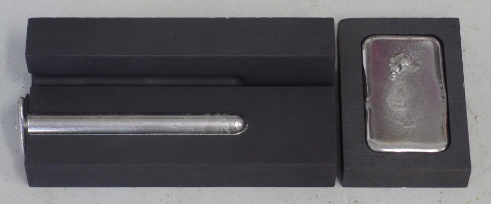
The experiments investigated a variety of bismuth alloys, and tried to determine the effects of adding lead, antimony, tin, and zinc. [Simplifier] mixed together each alloy in an electric furnace, cast it into a cylindrical mold, machined the resulting rod to a uniform length, and used tin-bismuth solder to connect each end to a brass electrode. To test each composition, one end of the cylinder was cooled with ice while the other was held in boiling water, then resistance was measured under this known temperature gradient. According to the Wiedemann-Franz law, this was enough information to approximate the metal’s thermal conductivity.
Armed with the necessary data, [Simplifier] was able to calculate each alloy’s thermoelectric efficiency coefficient. The results showed some useful information: antimony is a useful additive at about 5% by weight, tin and lead created relatively good thermoelectric materials with opposite polarities, and zinc was useful only to improve the mechanical properties at the expense of efficiency. Even in the best case, the thermoelectric efficiency didn’t exceed 6.9%, which is nonetheless quite respectable for a homemade material.
This project is a great deal more accessible for an amateur than previous thermoelectric material research we’ve covered, and a bit more efficient than another home project we’ve seen. If you just want to get straight to power generation, check out this project.
A Toolchanging Delta 3D Printer
We’ve seen quite a few delta 3D printers, and a good number of toolchanging printers, but not many that combine both worlds. Fortunately, [Ben Wolpert]’s project fills that gap with a particularly elegant and precise delta toolchanger.
The hotend uses three steel spheres and triangular brackets to make a repeatable three-point contact with the toolhead frame, and three pairs of corresponding magnets hold it in place. The magnets aren’t in contact, and the three magnets on the toolhead are mounted in a rotating ring. A motorized pulley on the printer’s frame drives a cable which runs through a flexible guide and around the rotating ring.
The whole setup is very reminiscent of the Jubilee toolchanging system, except that in this case, the pulley rotates the ring of magnets rather than a mechanical lock. By rotating the ring of magnets about 60 degrees, the system can move the pairs of magnets far enough apart to remove the hotend without much force.
The rest of the toolchanging system is fairly straightforward: each tool’s parking area consists of two metal posts which slot through corresponding holes in the hotend’s frame, and the motherboard uses some RepRapFirmware macros to coordinate the tool changes. The only downside is that a cooling fan for the hotend still hadn’t been implemented, but a desk fan seemed to work well enough in [Ben]’s tests. The files for the necessary hardware and software customizations are all available on GitHub.
We’ve only seen a similar toolchanging system for a delta printer once before, but we have seen a great variety of toolchangers on the more common Cartesian systems. Don’t like the idea of changing extruders? We’ve also seen a multi-extruder printer that completely eliminates tool switching.
A Constant-Fraction Discriminator For Sub-Nanosecond Timing
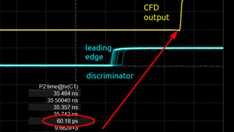
Detecting a signal pulse is usually basic electronics, but you start to find more complications when you need to time the signal’s arrival in the picoseconds domain. These include the time-walk effect: if your circuit compares the input with a set threshold, a stronger signal will cross the threshold faster than a weaker signal arriving at the same time, so stronger signals seem to arrive faster. A constant-fraction discriminator solves this by triggering at a constant fraction of the signal pulse, and [Michael Wiebusch] recently presented a hacker-friendly implementation of the design (open-access paper).
A constant-fraction discriminator splits the input signal into two components, inverts one component and attenuates it, and delays the other component by a predetermined amount. The sum of these components always crosses zero at a fixed fraction of the original pulse. Instead of checking for a voltage threshold, the processing circuitry detects this zero-crossing. Unfortunately, these circuits tend to require very fast (read “expensive”) operational amplifiers.
This is where [Michael]’s design shines: it uses only a few cheap integrated circuits and transistors, some resistors and capacitors, a length of coaxial line as a delay, and absolutely no op-amps. This circuit has remarkable precision, with a timing standard deviation of 60 picoseconds. The only downside is that the circuit has to be designed to work with a particular signal pulse length, but the basic design should be widely adaptable for different pulses.
[Michael] designed this circuit for a gamma-ray spectrometer, of which we’ve seen a few examples before. In a spectrometer, the discriminator would process signals from photomultiplier tubes or scintillators, such as we’ve covered before.