
Minecraft hit the PC gaming scene as an alpha release on May 17, 2009. Something about the open world, the crafting system, and the various modes of gameplay made it an instant hit. Since then Minecraft become one of the best selling video games of all time, inspiring thousands of hacks, mods, and projects. This week’s Hacklet highlights some of the best Minecraft projects on Hackaday.io!
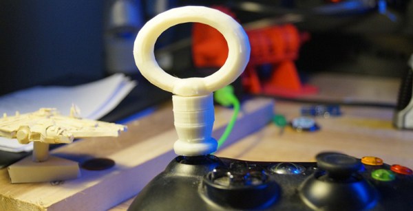
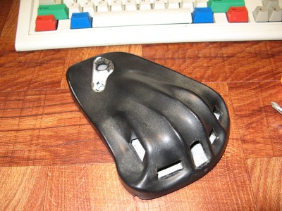 We start with [Toulon] and his MineCraft Sidecar Keypad. The Mystify Claw was originally designed as an alternative input device for First Person Shooter (FPS) games. It may look like a mouse, but the claw has no balls or lasers. It provides a 10 button “cradle” for the left hand. Some folks liked the claw, but for many it quickly became a dust collector. [Toulon] resurrected this old input device as an awesome Minecraft controller. He started by yanking all the old electronics, replacing the claw’s brain with the Teensy 2.0, a favorite of keyboard hackers everywhere. New buttons and a slew of new Teensy code made things perfect for mining.
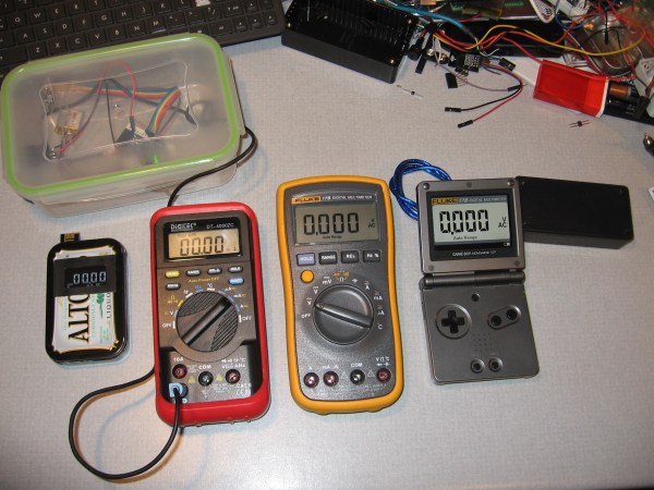
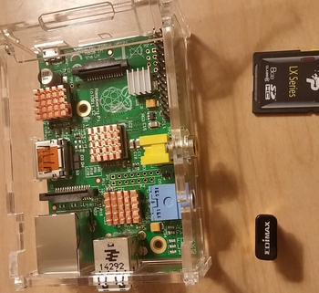 Next up is [Thomas] and his Raspberry Minecraft Server. The Raspberry Pi has long been a hacking platform for Minecraft. The official Raspberry Pi edition of Minecraft is easy to get running, and great for hours of fun. You can also run a Minecraft server on the Pi, which is exactly what [Thomas] is doing. He’s set his Raspberry Pi up with a WiFi dongle and a battery pack. With a bit of configuration, this allows the Pi to become the center of a wireless Lan party. On batteries, the Pi will run for about five hours of continuous gaming. Details for [Thomas’] project are a bit light right now, but that’s only because he just literally started documenting and uploading his project as we’re going to press. Give him a few days and he’ll have everything filled in!
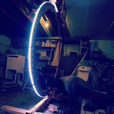
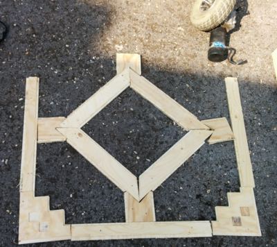 [GPPK] brings a bit of Minecraft into the real world with Full Size Wireless Redstone Lamp. Inspired by smaller models of the Minecraft redstone lamp, [GPPK] decided to build a life-sized version. “Life-sized” in this case is about 1 cubic meter. That’s a BIG lamp! [GPPK] designed the shell of the lamp in Sketchup, and cut the sides out using a gantry style CNC machine. The structure will be held together with 3D printed connectors, while a Raspberry Pi will provide the brains. Turning the lamp on will be as simple as turning on a switch in-game in Minecraft. [GPPK] has been a bit slow lately with updates on the project. If you know [GPPK] let ’em know that we’re anxiously awaiting some info!
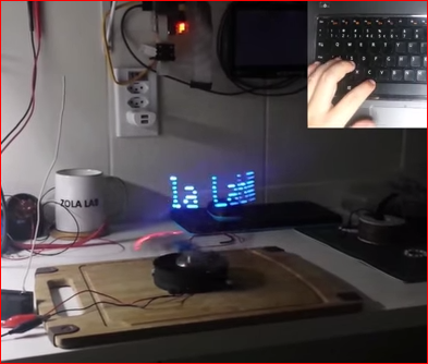
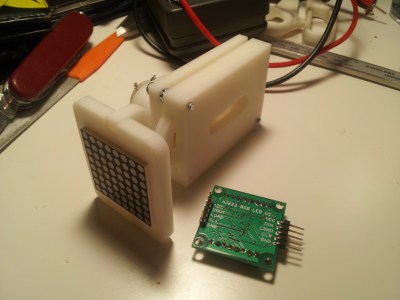
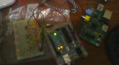 Finally, we have [Simon] and Raspberry Pi Python Controller. One of the best ways to get kids hooked on hacking and electronics is to show them how simple circuits can lead to big changes. What better way to do that than wiring up a simple push button controller for Minecraft? [Simon] used an Arduino paired to a Raspberry Pi with a serial over USB connection. Buttons wired to the Arduino are sent through the serial link to the Pi, where a python script fires off actions based on the serial data. [Simon] has tested his script with Mincraft Pi Edition, and is happy to report back that it works great.
Do you know what’s missing from this Hacklet? Your Minecraft project! It’s not too late though – upload your info to Hackaday.io, and we might just add it to our brand new Minecraft Projects List!
Well, it’s just about quitting time here in the Hackaday Mine. As long as the creepers don’t get us, we’ll be back next week. Same hack time, same hack channel, bringing you the best of Hackaday.io!

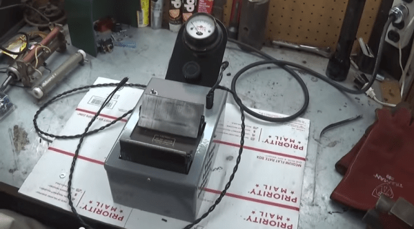
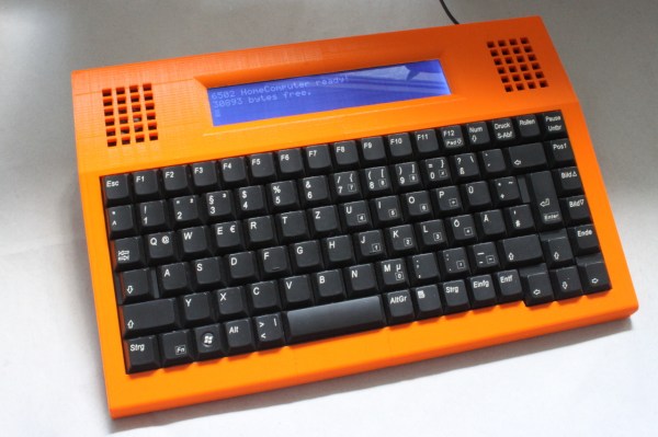
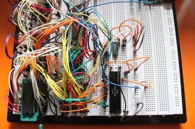 [Dirk] has some great documentation to go with his computer. He started with a classic MOS 6502 processor. He surrounded the processor with a number of support chips correct for the early 80’s period. RAM is easy-to -use static RAM, while ROM is handled by UV erasable EPROM. A pair of MOS 6522 Versatile Interface Adapter (VIA) chips connect the keyboard, LCD, and any other peripherals to the CPU. Sound is of course provided by the 6581 SID chip. All this made for a heck of a lot of wires when built up on a breadboard. The only thing missing from this build is a way to store software written on the machine. [Dirk] already is looking into ways to add an SD card interface to the machine.
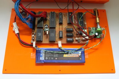 The home building didn’t stop there though. [Dirk] designed and etched his own printed circuit board (PCB) for his computer. DIY PCBs with surface mount components are easy these days, but things are a heck of a lot harder with older through hole components. Every through hole pin and via had to be drilled, and soldered to the top and bottom layers of the board. Not to mention the fact that both layers had to line up perfectly to avoid missing holes! To say this was a lot of work would be an understatement.
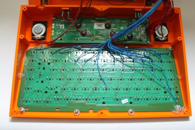 [Dirk] designed a custom 3D printed case for his computer and printed it out on his Ultimaker. To make things fit, he created his design in halves, and glued the case once printing was complete.


