Droning On: Maiden Flights

do-55

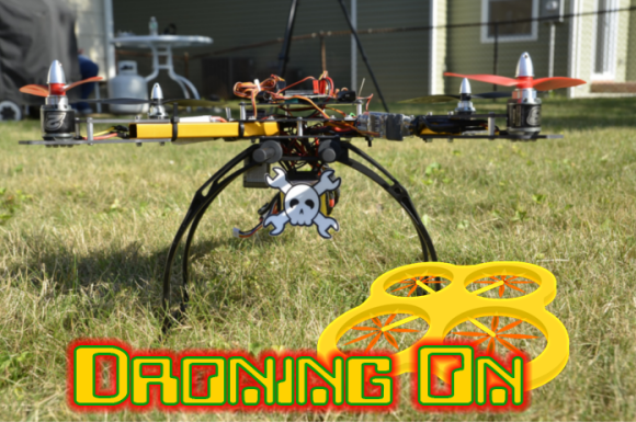
When we last left off, the Hackaday Drone Testbed was just a box of parts on workbench. Things have changed quite a bit since then! Let’s get straight to the build.

With the arms built and the speed controls soldered up, it was simply a matter of bolting the frame itself together. The HobbyKing frame is designed to fold, with nylon washers sliding on the fiberglass sheets. I don’t really need the folding feature, so I locked down the nylock nuts and they’ve stayed that way ever since. With the arms mounted, it was finally starting to look like a quadcopter.

drone1

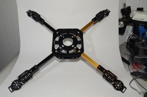
Using the correct screws, the motors easily screwed into the frames. I did have to do a bit of filing on each motor plate to get the motor’s screw pattern to fit. The speed controls didn’t have a specific mount, so I attached them to the sides of the arms with double-sided tape and used some zip ties to ensure nothing moved. In hindsight I should have mounted them on the top of the arms, as I’m planning to put LED light strips on the outside of edges of the quad. The LEDs will help with orientation and ensure a few UFO sightings during night flights.

Power distribution is a major issue with multicopters. Somehow you have to get the main battery power out to four speed controls, a flight controller, a voltage regulator, and any accessories. There are PCBs for this, which have worked for me in the past. For the Hackaday Testbed, I decided to go with a wiring harness. The harness really turned out to be more trouble than it was worth. I had to strip down the wires at the solder joint to add connections for the voltage regulator. The entire harness was a bit longer than necessary. There is plenty of room for the excess wire between the main body plates of the quad, but all that copper is excess weight the ‘bench’ doesn’t need to be carrying. The setup does work though. If I need to shed a bit of weight, I’ll switch over to a PCB.

Click past the break to read the rest of the story.

Continue reading “Droning On: Maiden Flights”

LED Water Wheel Display Is Dekatron-tastic!

led-ring-final

Sometimes, it’s the simple things that mesmerize. [JohnS_AZ] has created a simple dekatron style LED ring, but we can’t seem to stop watching his video. [John’s] LED ring began as a visual indicator for his Hackaday Prize entry, a water consumption display. Judging by his website, [John] is a bit of a display nut. Nixie tubes and huge clocks feature prominently.

We’ve seen plenty of LED projects using the trusty 74xx595 8-bit shift register. [John] personally isn’t a fan, as the entire chip is only rated to drive about 50mA. While hackers routinely push the chip several times past this limit, [John] found a chip designed for the task in the Texas Instruments TLC59282 16 channel constant current LED driver. (PDF link) While more expensive than the ‘595, the 59282 makes life much easier. Only one resistor is needed at the chip’s current sense pin, rather than a current-limiting resistor for each LED. The 59282 also provides a blank input, which is perfect for driving with PWM.

[John] designed a simple PCB with a the 59282 driving a ring of 16 LEDs. While he waited for the boards to come in, he wrote some test code for a Microchip PIC16F1509. [John’s] code is not optimized, but that makes it easy to see exactly which bit patterns he’s writing to the LEDs. It all makes for a great demo, and reminds us of those old Dekatron tubes.
It’s the demo video that makes this project. Click past the break and give it a watch. After several long days of judging entries, a really nice LED ring might be just what the doctor ordered.

Continue reading “LED Water Wheel Display Is Dekatron-tastic!”

Thumbnail that say The Hacklet

Hacklet #12 – Last Minute Hackaday Prize Submissions

12

If hackers and engineers are notorious for anything, it’s for procrastinating. Many of us wait until the absolute last-minute to get things done. The Hackaday Prize has proved to be no exception to that. Anyone watching the newest projects could see the entries fly in the last few days. Let’s take a quick look at a few.

handuino

[Cyrus Tabrizi] submitted Handuino just a few short hours before the deadline. Handuino is an Arduino based human interface device. You can use it to control anything from R/C cars to 3D printers, to robots to Drones. Input is through the joystick, switches, and buttons, and output through the on-board 2.2″ LCD. Projects can interface to the Handuino via a USB port, or an XBEE radio. Nice Work [Cyrus].

bionicYoSelf

[txyz.info] wants to make us more human than human with Bionic Yourself, an implantable device to make you a bionic superhero. [txyz] plans to use sensors such as an electromagnetic field sensor, accelerometers, and Electromyography (EMG) muscle activity detectors. The idea is to not only sense the implanted wearer, but the world around them. The wearer can then use an embedded Bluetooth radio to send commands. The entire system runs on the Arduino platform, so updating your firmware will be easy. Not everyone has a charging port, so [txyz] has included wireless battery charging in the system.

HAD-alarm-clock[Laurens Weyn] wants to wake us all up with Overtime: the internet connected alarm clock. Overtime is a Raspberry PI powered clock with a tower of 7 segment displays. The prototype displays were sourced from an old exchange rate sign. Overtime does all the normal clock things, such as display the time, and date. It even allows you to set and clear alarms. The display is incredible – there are enough pixels there to play Tetris. Overtime is currently running on an Arduino Mega, but [Laurens] plans to move to a Raspberry PI and hook into the internet for information such as Google calender events.

We’re going to cut things a bit short this week. Your work is done (for now) but for the Hackaday staff, the work is just beginning. We’re already on task, reviewing the entries, and picking which submissions will move on to the next round. Good luck to everyone who entered.

As always, See you in next week’s Hacklet. Same hack time, same hack channel, bringing you the best of Hackaday.io!

Sparkfun Ships 2000 MicroViews Without Bootloaders

microview-fail

Everyone has a bad day right? Monday was a particularly bad day for the folks at Sparkfun. Customer support tickets started piling up, leading to the discovery that they had shipped out as many as 1,934 MicroViews without bootloaders.

MicroView is the tiny OLED enabled, Arduino based, microcontroller system which had a wildly successful Kickstarter campaign earlier this year. [Marcus Schappi], the project creator, partnered up with SparkFun to get the MicroViews manufactured and shipped out to backers. This wasn’t a decision made on a whim, Sparkfun had proven themselves by fulfilling over 11,000 Makey Makey boards to backers of that campaign.

Rather than downplay the issue, Sparkfun CEO [Nathan Seidle] has taken to the company blog to explain what happened, how it happened, and what they’re going to do to make it right for their customers. This positions them as the subject of our Fail of the Week column where we commiserate instead of criticize.

First things first, anyone who receives an affected MicroView is getting a second working unit shipped out by the beginning of November. Furthermore, the bootloaderless units can be brought to life relatively easily. [Nate] provided a hex file with the correct bootloader. Anyone with an Atmel AVR In-System Programming (ISP) programmer and a steady hand can bring their MicroView to life. Several users have already done just that. The bootloader only has to be flashed via ISP once. After that, the MicroView will communicate via USB to a host PC. Sparkfun will publish a full tutorial in a few weeks.

Click past the break to read the rest of the story.

Continue reading “Sparkfun Ships 2000 MicroViews Without Bootloaders”

When Worlds Collide: 68008 Bootstrapped By An Arduino Uno

68008-ardu

[Peter Bjornx] brings classic microprocessors and modern microcontrollers together with his Arduino bootstrapped 68008 computer. The Motorola 68008 is the 8-bit external bus version of the well-known 68000 (or 68k) microprocessor. A friend gave [Peter] one of these chips, so he built a simple computer around it.

This isn’t one of those clean retrocomputers with every connection carefully planned out and wire wrapped. [Peter’s] created a true hack – a working 68k system on a breadboard created with whatever he had on hand at the time. The real gem of this system is the ROM. [Peter] replaced an EPROM chip with an Arduino.

In the not-so-good-old-days, microprocessors (and many microcontrollers) ran from an external ROM chip. This often was a UV-erasable EPROM. Carefully compiled code was burned into the EPROM with a device programmer. If the code wasn’t perfect, the EPROM had to be pulled and placed under a UV lamp for 20 minutes or so to erase it before it was time to try again. EPROM emulators were available, but they were way too expensive for the hobbyist.

Thankfully those days are far behind us now with the advent of EEPROM and then Flash. [Peter] didn’t want to revisit the past either, so he wrote a simple Arduino sketch which allowed it to act as an EPROM emulator, including address logging via the serial port.

The design still caused [Peter] some headaches, though. His major problem was a classic 68k issue, /DTACK timing. /DTACK or Data Transfer Acknowledge is one of several bus control signals used by the 68k. When the 68k performs a read from the data bus, it waits for /DTACK before it transfers data. The Arduino was too slow to release /DTACK in this case, which caused the 68k to think every read was immediately completed. There is a much clearer explanation of the 68k bus cycles on this Big Mess O Wires page. [Peter’s] solution was simple – a D flip-flop connected to the address strobe took care of the timing issues.

It took quite a bit of tinkering, but the system eventually worked. Peter was able to run the 68008 from its reset vector into a simple loop using the Arduino. It’s only fitting that the 68k program loaded by the Arduino was an LED blinker, everyone’s favorite hardware Hello World.

Thanks [Robert!]

Lost PLA Casting With A Little Help From Your Microwave

lost-pla

[Julia and Mason] have been perfecting their microwave-based lost PLA casting technique over at Hackaday.io. As the name implies, lost PLA is similar to lost wax casting techniques. We’ve covered lost PLA before, but it always involved forges. [Julia and Mason] have moved the entire process over to a pair of microwaves.

Building on the work of the FOSScar project, the pair needed a way to burn the PLA out of a mold with a microwave. The trick is to use a susceptor. Susceptors convert the microwave’s RF energy into thermal energy exactly where it is needed. If you’ve ever nuked a hot pocket, the crisping sleeve is lined with susceptor material. After trying several materials, [Julia and Mason] settled on a mixture of silicon carbide, sugar, water, and alcohol for their susceptor.

The actual technique is pretty simple. A part printed in PLA is coated with susceptor. The part is then placed in a mold made of plaster of paris and perlite. The entire mold is cooked in an unmodified household microwave to burn out the PLA.

A second microwave with a top emitter is used to melt down aluminum, which is then poured into the prepared mold. When the metal cools, the mold is broken away to reveal a part ready to be machined.

We think this is a heck of a lot of work for a single part. Sometimes you really need a metal piece, though. Until metal 3D printing becomes cheap enough for everyone to do at home, this will work pretty well.

TFT LCDs Hit Warp Speed With Teensy 3.1

[Paul Stoffregen], known as father of the Teensy, has leveraged the Teensy 3.1’s hardware to obtain some serious speed gains with SPI driven TFT LCDs. Low cost serial TFT LCDs have become commonplace these days. Many of us have used Adafruit’s TFT LCD library  to drive these displays on an Arduino. The Adafruit library gives us a simple API to work with these LCDs, and saves us from having to learn the intricacies of various driver chips.

[Paul] has turbocharged the library by using hardware available on Teensy 3.1’s 32 Freescale Kinetis K20 microcontroller. The first bump is raw speed. The Arduino’s ATmega328 can drive the SPI bus at 8MHz, while the Teensy’s Kinetis can ramp things up to 24MHz.

Speed isn’t everything though. [Paul] also used the Freescale’s 4 level FIFO to buffer transfers. By using a “Write first, then block until the FIFO isn’t full” algorithm, [Paul] ensured that new data always gets to the LCD as fast as possible.

Another huge bump was SPI chip select. The Kinetis can drive up to 5 SPI chip select pins from hardware. The ATmega328 doesn’t support chip selects. so they must be implemented with GPIO pins, which takes even more time.

The final result is rather impressive. Click past the break to see the ATmega based Arduno race against the Kinetis K20 powered Teensy 3.1.

Paul’s library is open source and available on Github.

Continue reading “TFT LCDs Hit Warp Speed With Teensy 3.1”