 This week on the Hacklet, we’re spending some time looking at bugs and fire!
 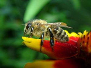 First up we have [Noel] who is saving the bees with Bee-O-Neo-Tweet-O. Bees are incredibly important, both to Earth’s ecosystem and the food chain we humans need to survive. Unfortunately bees are also sensitive to some of the chemicals humans dump into the atmosphere. Sometimes it results in colored honey, but more often than not it’s detrimental to the bees.
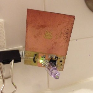
Neonicotinoids are a class of insecticide that has been causing problems to hives near where they are used. [Noel] is banking on sensors created with bismuth electrodes to detect the chemical near the entrance to hives. The data can be collected by beekeepers all over the world and sent to a central server. He’s using an Arduino Yun as a WiFi connected base station. Each individual hive has an Adafriut Trinket and a 433MHz radio link to send data to the base. [Noel] is even hoping to detect individual bees by the sound of their wings beating.
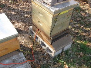
[Ken] is keeping his own bees, and wants to monitor more than just chemicals. His honeybee hive monitoring system keeps track of the temperature and weight (and thus the honey produced) by his hives. Rather than buy an expensive load cell setup, [Ken] modified a standard digital bathroom scale to suit his needs. The insects connect to the IOB (Internet of Bees) with a bit of help from the Apitronics platform and a BeagleBone Black. Ken even added a solar-powered weather station with the Apitronics system.
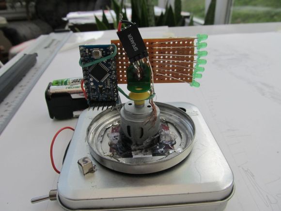
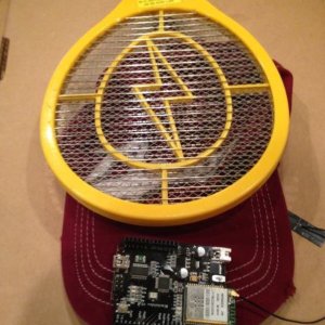 [Mike] is taking a slightly different approach. He doesn’t want to save the bugs, he wants to kill the ones that bug him! [Mike] doesn’t want to get his hands dirty, so he’s created Lazy Killer 9000 for easy bug killing. Lazy Killer uses the business end of an electrified fly swatter to do its work. This project wouldn’t be complete without an Arduino, so [Mike] is adding one, as well as a WiFi shield. The entire system will have a friendly interface to turn the juice on. One of the best features of Lazy Killer is the internet connected kill count. [Mike] knows that there aren’t any bugs in the vacuum of space, so he’s entered Lazy Killer in The Hackaday Prize.
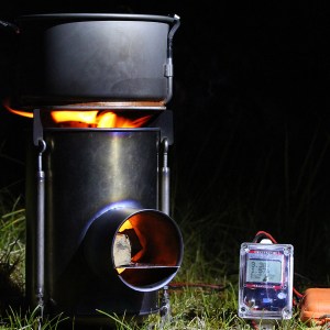
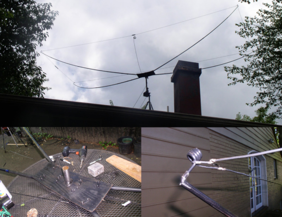
From bugs, we move on to Fire! [mr.jb.swe] needed a reliable portable power source. He found it in LiFePO4 batteries, but still needed a way to charge them. Toward that end he’s created The Multicharger, a watt meter and charger which can be powered from solar, wind, or thermometric power. A Powerpot X provides the fire and the power to charge the batteries. [mr.jb.swe’s] charger converts that into the standard constant current->constant voltage charging system needed by lithium chemistry batteries. The Multicharger isn’t a complete battery management system yet, but it’s well on its way.
Unity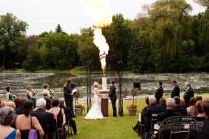 candles have become a staple at wedding ceremonies.[Quinn] has taken things to the next level and beyond with this take on the classic unity candle. This candle throws fireballs 30 feet into the sky! We covered the candle back in June, but [Quinn] has been busy since then. With over 20 updates, [Quinn] has created one of the most well documented projects on Hackaday.io. Of course, being that this project is dealing with propane and monstrous fires, [Quinn] mentions you shouldn’t try unless you really know what you’re doing. Don’t set any brides on fire! That’s it for this week’s Hacklet! Tune in next week, same hack time, same hack channel, for more of the best of Hackaday.io!