Over-engineering Ding Dong Ditch

One day, [Samy]’s best friend [Matt] mentioned he had a wireless doorbell. Astonishing. Even more amazing is the fact that anyone can buy a software defined radio for $20, a small radio module from eBay for $4, and a GSM breakout board for $40. Connect these pieces together, and you have a device that can ring [Matt]’s doorbell from anywhere on the planet. Yes, it’s the ultimate over-engineered ding dong ditch, and a great example of how far you can take practical jokes if you know which end of a soldering iron to pick up.

Simply knowing [Matt] has a wireless doorbell is not enough; [Samy] needed to know the frequency, the modulation scheme, and what the doorbell was sending. Some of this information can be found by looking up the FCC ID, but [Samy] found a better way. When [Matt] was out of his house, [Samy] simply rang the doorbell a bunch of times while looking at the waterfall plot with an RTL-SDR TV tuner. There are a few common frequencies tiny, cheap remote controls will commonly use – 315 MHz, 433 MHz, and 900 MHz. Eventually, [Samy] found the frequency the doorbell was transmitting at – 433.8 MHz.

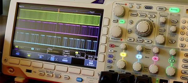
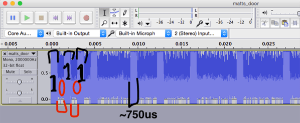
After capturing the radio signal from the doorbell, [Samy] looked at the audio waveform in Audacity. It looked like this doorbell used On-Off Keying, or just turning the radio on for a binary ‘1’ and off for a binary ‘0’. In Audacity, everything the doorbell transmits becomes crystal clear, and with a $4 434 MHz transmitter from SparkFun, [Samy] can replicate the output of the doorbell.

For the rest of the build, [Samy] is using a mini GSM cellular breakout board from Adafruit. This module listens for any text message containing the word ‘doorbell’ and sends a signal to an Arduino. The Arduino then sends out the doorbell code with the transmitter. It’s evil, and extraordinarily over-engineered.

Right now, the ding dong ditch project is set up somewhere across the street from [Matt]’s house. The device reportedly works great, and hopefully hasn’t been abused too much. Video below.
Continue reading “Over-engineering Ding Dong Ditch”

Fail Of The Week: Teddy Top And Fourteen Fails

Last summer, [Quinn] made the trip out to KansasFest, the annual Apple II convention in Kansas City, MO. There, she picked up the most modern Apple II system that wasn’t an architecturally weird IIGS: she lugged home an Apple IIc+, a weird little machine that looks like an old-school laptop without a screen.

Not content with letting an old computer just sit on a shelf looking pretty, [Quinn] is working on a project called the Teddy Top. ‘Teddy’ was one of the code names for the Apple IIc, and although add-ons to turn this book-sized computer into something like a laptop existed in the 80s, these solutions have not withstood the test of time. [Quinn] is building her own clamshell addition to her IIc+, and somehow failing at something she’s done hundreds of times before.

While the IIc+ has an NTSC composite output, the super-special video add-ons for the IIc+ used a DB15 expansion connector. Here, any add-on could access video sync signals, the a sound signal from the audio circuit, and even a +12V line that could drive loads up to 300 mA. It just so happened the display [Quinn] is using for this project runs at 12V, 200 mA. Everything was great, but as a worthy trustee of this computer’s Earthly existence, [Quinn] thought a bit of current limiting should be included in her addon. She designed a circuit around an NPN power transistor, that would allow the display to draw power until the load was around 250mA. After that, the transistor would start dumping excess power as heat. Yes, a fuse would be better. [Quinn] calls this Fail #1. There are thirteen more to go.

Continue reading “Fail Of The Week: Teddy Top And Fourteen Fails”

The ERIC-1 Microcomputer

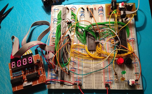
Everyone is having a go at building their own 8-bit 80s-era microcomputer now, and [Petri] thought he would throw his hat into the ring with ERIC-1, a homebrew, 6502-based computer that’s running at about 2MHz.

We’re about 30 or 40 years ahead of the game compared to the old-school 6502 designs, and [Petri] decided to capitalize on that. Instead of a separate ROM, VIA, and other peripherals, [Petri] is connecting a microcontroller directly to the data and address pins. This is a technique we’ve seen before, and [Petri] is doing it right: the micro and 6502 share 64k of RAM, with the ROM stored in the micro’s Flash. Video (PAL in this case) is handled by the ATMega, as is clocking and halting the CPU.

There were a few changes [Petri] made along the way to make this microcomputer a little more useful. One of the biggest changes was switching out the old NMOS Rockwell 6502 with the modern CMOS W65C02 from Western Design Center. The CMOS variant is a fully static design, keeping the registers alive even if the clock is stopped and making single-stepping and halting the CPU easier.

The CMOS variant also has a Bus Enable (BE) pin. Like similar pins on later, more advanced processors, this pin puts the address, data, and R/W pins into a high impedance state, giving other peripherals and microcontrollers the ability to write to RAM, peripherals, or anything else. It’s a handy feature to have if you’re using a microcontroller for everything except the CPU.

It’s already a great build, and since [Petri] has the skills to program this 8-bit ‘duino game, he’s sure to come up with something even better for this computer.

Oh, if you’re looking for something even cooler than a 3-chip 6502, there’s a bunch of stuff over on hackaday.io you should check out. Everything from 4-bit computers built from discrete components to dual AVR board can be found there.

The Epoch Christmas Tree

It’s that time of the year again, and the halls are being decked with trees, the trees covered in lights, and everyone working in retail is slowly going insane from Christmas songs piped over the PA. [Dan] has a tree and a bunch of programmable LEDs, but merely pumping jollity down that strip of LEDs wouldn’t be enough. The Nerd Quotient must be raised even higher with a tree that displays a Unix timestamp.

This build was inspired by an earlier, non-tree-based build that displays Unix time on a 32 LED array. That build used an ATMega328p for toggling LEDs on and off. This time around, [Dan] is using a dedicated LED controller – the AllPixel – that just wrapped up a very successful Kickstarter campaign. The AllPixel is, in turn, controlled by a Raspberry Pi running the BiblioPixel library,

The tree displays the current time stamp in binary across 32 spaces, with green representing a ‘one’ and a red representing ‘zero’. The top of the tree is the least significant bit, but in case [Dan] gets tired of the bottom of the tree staying completely still for the rest of this holiday season, he can switch the order making the base of the tree the LSB.

Video below.

Continue reading “The Epoch Christmas Tree”

12 Mbps Communication Between A PC And MCU

The world of hobby electronics have only started putting USB in projects for the last few years, and right now, pushing 1.5 Mbps down a USB port is good enough for most cases. This isn’t true for all cases; that’s a terrible data rate, really, and to get the most out of a USB connection, you can at least move up to USB Full Speed and 12 Mbps.

[Linas] is using the STM32F4 microcontroller for this example, an extremely large and very capable chip. [Linas] is using FTDI’s FT2232D USB UART to send data from an SPI port over USB. This chip does support 12 Mbps, but only after a few additions; an external EEPROM must be connected to the FTDI chip to provide a USB 2.0 device descriptor, otherwise the connection between the microcontroller and a computer is limited to 1.5 Mbps. Even using the USB on the STM32 would be a bottleneck in this case; [Linas] is moving data out of the processor using only the DMA controller – using the USB on the STM32 would eat up processor cycles in the microcontroller.

Thanks to the DMA controller inside the STM32, the microcontroller is capable of sending and receiving data through SPI at the same time. The STM32 is capable of reading and writing to the Tx and Rx buffer at the same time, but the computer is only capable of half-duplex operation – it can only read or write at any one time. [Linas] is setting up the DMA controller on the STM32 as a circular mode, putting everything in the buffer into the FTDI chip, and reading everything sent from the computer back into the STM32’s memory. After counting off the correct number of packets. the controller resets everything, moves the circular buffer back to the beginning, and starts the whole process over again.

The circuit was prototyped with an STM Discovery board. With Labview, [Linas] can see the bits coming out of the microcontroller, and send some bits back to the micro over USB. [Linas] has an extraordinarily detailed video tutorial on this project. You can check that out below.

Continue reading “12 Mbps Communication Between A PC And MCU”

Clap On! A Breadboard

The Clapper™ is a miracle of the 1980s, turning lights and TVs on and off with the simple clap of the hands, and engraving itself into the collective human unconsciousness with a little jingle that implores – nay, commands – you to Clap On! and Clap Off! [Rutuvij] and [Ayush] bought a clap switch kit, but like so many kits, this one was impossible to understand; building the circuit was out of the question, let alone understanding the circuit. To help [Rutuvij] and [Ayush] out, [Rafale] made his own version of the circuit, and figured out a way to explain how the circuit works.

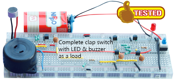
While not the most important component, the most obvious component inside a Clapper is a microphone. [Rafale] is using a small electret microphone connected to an amplifier block, in this case a single transistor.

The signal from the microphone is then sent to the part of the circuit that will turn a load on and off. For this, a bistable multivibrator was used, or as it’s called in the world of digital logic and Minecraft circuits, an S-R flip-flop. This flip-flop needs two inputs; one to store the value and another to erase the stored value. For that, it’s two more transistors. The first time the circuit senses a clap, it stores the value in the flip-flop. The next time a clap is sensed, the circuit is reset.

Output is as simple as a LED and a buzzer, but once you have that, connecting a relay is a piece of cake. That’s the complete circuit of a clapper using five transistors, something that just can’t be done with other builds centered around a 555 timer chip.

Making T-Glase Crystal Clear

There are 3D printing filaments out there with a lot of interesting properties. Whether it’s the sanded-down MDF feel you get from Laywood, the stretchy and squishy but somehow indestructible feel of Ninjaflex, or just regular ‘ol PLA, there’s a filament out there for just about any use. Even optically clear printed objects. Yes, you can now do some post-processing on printed parts to make T-glase crystal clear.

The big advance allowing translucent parts to be made clear is a new product from Smooth-On that’s meant to be a protective and smoothing coating for 3D printed objects. With PLA, ABS, and powder printed parts, this coating turns objects shiny and smooth. Strangely – and I don’t think anyone planned this – it also has the same index of refraction as T-glase. This means coating an object printed with T-glase will render the layers invisible, smooth out the tiny bumps in the print, and turn a single-walled object clear.

There is a special technique to making clear objects with T-glase. The walls of the print must be a single layer. You’ll also want a perfect layer height on your print – you’re looking for cylindrical layers, not a nozzle that squirts out to the side.

The coating for the pictures above was applied on a makeshift lathe built out of an electric drill and a sanding pad. This gave the coating a nice, even layer until it dried. After a few tests, it was determined lenses could be printed with this technique. It might not be good enough for 3D printed eyeglasses, but it’s more than sufficient for creating windows for a model, portholes for an underwater ROV, or anything else where you want nothing but light inside an enclosure.