Capacitive Sensing Tutorial

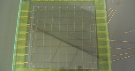
[Bertho]’s submission for the 74xx logic contest is really impressive. He designed a capacitive sensing touchpad using only 74xx and 40xx logic chips. We’re impressed with the build and his writeup is one of the best resources we’ve ever seen for capacitive sensing.

There are two ways to go about designing a capacitive touchpad. The first option is put a voltage through an RC circuit. Measure the voltage-time curve, and you have a measure of the capacitance of the circuit. The second method is setting up an RC circuit to change polarity after a threshold for C has been reached. Microprocessors only use one of these methods (AVR uses the first, PIC uses the second), but [Bertho] decided to implement both methods for unknown reasons we still respect.

The circuit [Bertho] designed has a 30MHz clock using only 74xx logic chips, an amazing feat in itself. An 8×8 channel panel was fabricated and the whole build connects to a computer over RS-232.

The finished build is good enough has 64 points of resolution and is able to detect proximity very well. The touchpad is even able to recognize when a pen is placed on the panel. Check out the video after the break for the walk through and demo of this amazing build.
Continue reading “Capacitive Sensing Tutorial”

Improvised Metal Lathe

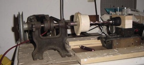
[McKGyver] needed a few parts manufactured. Instead of going the normal route – finding friends with machine tools or paying a machine shop, he improvised a rudimentary metal lathe.

As much as we love 3D printers, they’re not the be-all, end-all solution for everything. Sometimes, you need to get a little dirty and do it the old-fashioned way. [McKGyver] needed a way to produce aluminum shaft couplers to join stepper motors to lead screws. A 1940s grinding wheel was used for the headstock. Since [McKGyver] only needed couplers of one size, he made a jig out of wood to attach the aluminum blanks to the spindle. A drill and a focuser from a photographic enlarger makes up the tailstock of the improvised lathe. The use of a camera focuser is pretty clever. Unless the equipment has been damaged, it’s guaranteed to move in a straight line. A small laser was used to align the drill.

The finished couplers were concentric to 0.005″. A ‘passable precision’ for his application, and a clever build that doesn’t involve moving a thousand pound South Bend lathe.

Interfacing With A PS/2 Mouse

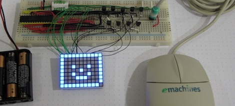
[David] sent in his implementation of reading a PS/2 mouse with a PIC microcontroller and some LED displays. Of course, this follows hot on the heels of using a PIC with a PS/2 keyboard so now might be the time to start digging out your old peripherals out of your junk pile.

[David] began his project trying to figure out how to connect a mouse to his breadboard. After hacking the plastic off a PS/2 mouse extension cord, he wired everything up according to the pinout. Programming the PIC to understand PS/2 commands was a little strange. [David] is used to having his microcontrollers provide the clock signal. The PS/2 protocol is a bit strange as the peripheral sets the clock. Since PS/2 is a bidirectional protocol, the mouse also accepts commands. The host – [David]’s PIC – must send the mouse a command to start sending movement data.

Because USB keyboards and mice are backwards compatible with PS/2 ports, [David] tried out a few USB mice with a USB to PS/2 adapter. Every attempt at using a USB mouse failed. Strangely, when a Bluetooth mouse was tried (via Bluetooth to USB to PS/2), everything worked perfectly. Check out [David]’s PIC mouse demo after the break.

Continue reading “Interfacing With A PS/2 Mouse”

ATtiny Hacks: Robot Halloween Costume

When it comes to Halloween costumes, [Michael] doesn’t like buying expensive and poorly made bits of cloth and fabric that resembles [random Disney character]. Last year, his son decided to be a robot for Halloween and although gray spray paint and dryer vent hose make a very good costume, that only goes so far. The robot needed lights, so [Michael] spent a little time on this build that blinks a few LEDs in a random pattern.

The build is very simple; an ATtiny13 drives two 74HC595 shift registers. The code – all 30-odd lines of it – uses the random() function to shift high or low values to the shift registers. After pausing for a little bit, the cycle continues and a new patterns of LEDs light up.

The electronics of the robot costume could be easily transferred to another theme – astronauts need LEDs on their backpack, and of course aliens communicate with blinking lights. In any event, it would avoid last year’s fiasco with a dozen [Heath Ledger] Jokers. Check out the video of [Michael]’s intergalactic robot son after the break.

Continue reading “ATtiny Hacks: Robot Halloween Costume”

ATtiny Hacks: Infrared Guidance And Navigation

After [trandi] got his hands on a cheap R/C helicopter he realized the difficulties in actually flying a remote control helicopter. Instead of giving up, he decided to reverse-engineer the infrared protocol and then build a decoder around an ATtiny that would send commands to another microcontroller using a serial connection.

The remote’s communications protocol was decoded with the help of a Freeduino and an IR remote analysis sketch [trandi] found on the Arduino website. After importing the data into Gnuplot, there was enough data to write a sketch in Processing to visualize the infrared pulses.

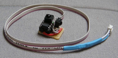
After figuring out the protocol of his remote control, [trandi] built a tiny circuit to decrypt the IR commands and send them over a serial link to another microcontroller. The ATtiny45-based build doesn’t take up very much space on the perfboard making it very easy to mount on any robot of his choosing. He ended up connecting it to a Lego NTX brick allowing him to use the helicopter remote with any Lego build he can dream up.

[trandi] invested a lot of work around a cheap remote control; if the remote broke, all would be for naught. This was remedied with an IR beacon that replicates the function of the remote. The beacon is based on an ATtiny13 and can serve as a stand-alone beacon for autonomous robots or can accept serial commands from a computer. Not a bad build if you ask us.

Why Wasn’t This Magnetic Cello Made In The 70’s?

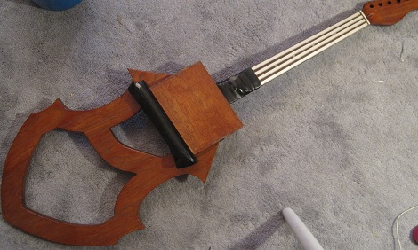
[magnetovore] made himself an electronic cello. Instead of pulling a few cello samples off of an SD card, he did it the old school analog way. The finished build is really impressive and leaves us wondering why we haven’t seen anything like this before.

[magnetovore] uses a permanent magnet to play each ‘string’. A lot of details are in this post and [magnetovore]’s provisional patent (PDF warning). From what we can gather, each string is a resistive ribbon sensor connected to a voltage controlled oscillator. The output of the VCO is sent to a variable gain amplifier that is controlled by a coil of wire and the magnetic ‘bow’.

From the video (after the break), [magnetovore] already has an amazing reproduction of the cello sound. It’s a bit electronic on the lowest parts of the C string, but with a little bit of processing it could definitely pass for an acoustic instrument. We’re left wondering why we haven’t seen anything like this cello before. VCOs and VGAs were the bread and butter of the old Moogs and even the ancient ondes martenot. Ribbon controllers were being attached to electronic instruments back in the 50’s, so we’re really at a loss on why a magnetic cello is new to us. If any Hack A Day readers have seen anything like this before, leave a message in the comments.

Continue reading “Why Wasn’t This Magnetic Cello Made In The 70’s?”

Laser Cut Clock Reminds Us Of A Spirograph

[Brian] from Louisville’s LVL1 hackerspace sent in this laser cut gear clock that’s almost unlike any other clock we’ve seen before. [Brian] also put up a wonderful Instructable for his build.

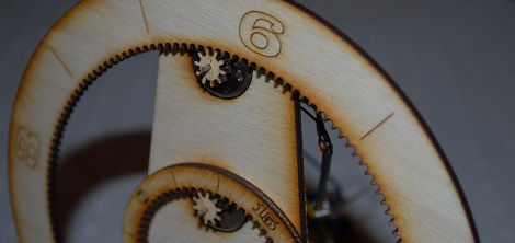
Since LVL1 got a better laser cutter a lot of neat projects have been piling up. [Brian] based his clock around two cheap stepper motors driven by a freeduino. A chronodot was used to keep accurate time. Making the gears, though, presented a few problems. While prototyping the gear clock face, it was apparent that the numbers should be oriented along a line coming from the center of the gear. The prototype also used 100 teeth and that didn’t translate well into a clock design. [Brian] designed the minute gear with 60 teeth, and the hour gear with 144 teeth so that each tooth would equal 5 minutes.

[Brian]’s clock is functionally similar to this $2500 gem, and certainly much less expensive even after the cost of the laser cutter is taken into account. Of course, the Spirograph clock keeps track of minutes so it may be worth upwards of $5k.