At first we laughed at the ridiculously over-the-top fume extraction system this hackerspace built for itself. Then we thought about seriously questionable donation rolls of solder some of the members managed to find and bring in. The kind of roll where the local greybeard assures you that a Californian State Trooper has permission to shoot you if you try to take it into the state, but damn does it solder well. They may be onto something is all we’re saying. But on a serious note, for a communal space like this one, a great air quality plan makes the place a lot more pleasant, if not safer at the same time.
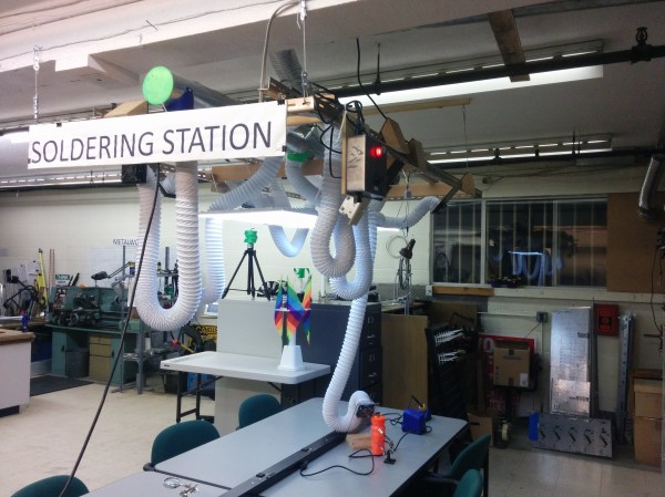
The build uses a regular boost fan for its main suction and pulls the fumes out to a place the members aren’t. Knowing hackerspaces that could be anything from an empty alley to vents on the building’s roof. It’s actually an interesting challenge to solve in a rented space (please share your own solutions for “daylighting” to the outside in the comments).
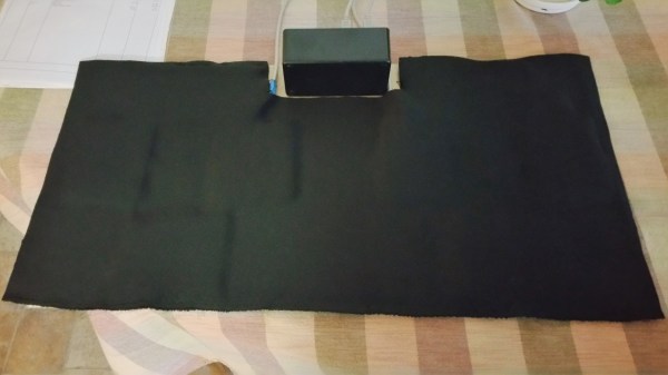
The frame is made from ducting and dryer hose. Since there aren’t really fittings for this. Most of the joints were designed in OpenSCAD and 3D printed. At each end of the tube a computer fan provides another little boost of airflow. We like the stands to position each end of the hose at the fume source. All of it is powered by a distribution box of their own making with the juice being fed with repurposed Ethernet cables to the fans at the ends of the hose.
It’s a nice build and likely extended the life of a few of the more electronically active members in the space. Especially if the retired radio enthusiasts decide to do their fifty year anniversary garage cleaning and gift upon the space their findings.
Formlabs makes a pretty dang good SLA printer by all accounts. Though a bit premium in the pricing when compared to the more humble impact of FDM printers on the wallet, there’s a bit more to an SLA printer. The reasoning becomes a bit more obvious when reading through this two part series on the design and testing of the Form 2.
It was interesting to see what tests they thought were necessary to ensure the reliable operation of the machine. For example the beam profile of every single laser that goes into a printer is tested to have the correctly shaped spot. We also thought the Talcum powder test was pretty crazy. They left a printer inside a sandblast cabinet and blasted it with Talcum powder to see if dust ingress could cause the printer to fail; it didn’t.
The prototyping section was a good read. Formlabs was praised early on for the professional appearance of their printers. It was interesting to see how they went from a sort of hacky looking monstrosity to the final look. They started by giving each engineer a Form 1 and telling them to modify it in whatever way they thought would produce a better layer separation mechanism. Once they settled on one they liked they figured out how much space they’d need to hold all the new mechanics and electronics. After that it was up to the industrial designer to come up with a look that worked.
They’re promising a third part of the series covering how the feedback from beta testing was directed back into the engineering process. All in all the Form 2 ended up being quite a good printer and the reviews have been positive. The resin from Formlab is a little expensive, but unlike others they still allow users to put the printer in open mode and use other resin if they’d like. It was cool to see their engineering process.
Everything from horrifying eBay purchases to work (horror) stories can be found in this thread. But you can learn something too. Did you know the correct way to fix a mercury switch stored in the incorrect orientation is to whack it against a table really hard?
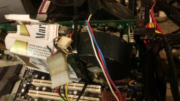
We enjoyed the cigarette box shroud used to fix a graphics card with a defective fan. We’re still not sure about the person who managed to Dremel bits off a graphics card and end up with a working PCI-e card. That one may be a troll.
Regardless, it’s a lot of fun, spanning the hilariously bad and the seriously impressive. We would not be surprised if some of these people met the devil at the crossroads for some soldering skill. Do any of you have an interesting or ugly repair to share? We’d love to see it.
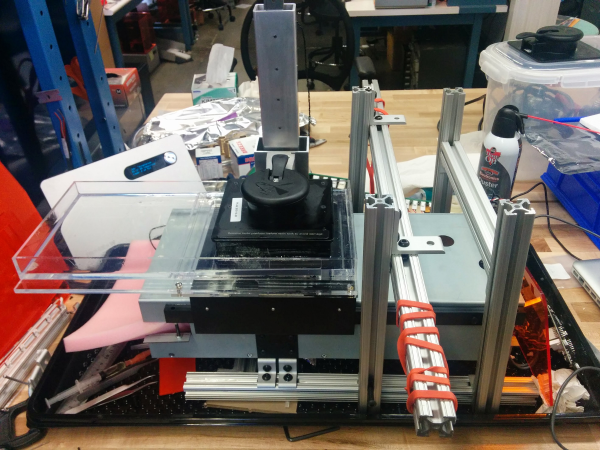
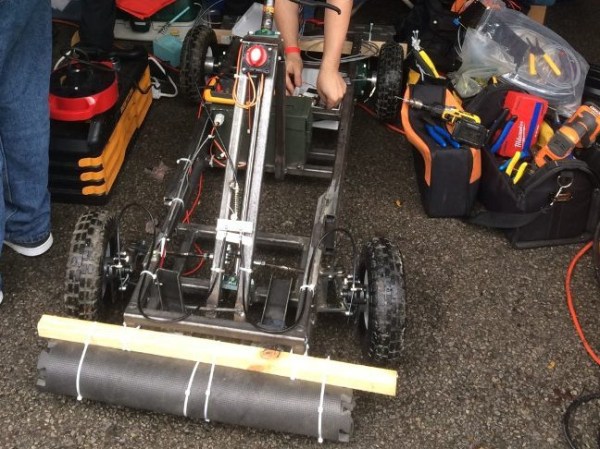
It wasn’t the first time his group had worked together on something a little different, such as a robot that can deploy an antenna by climbing poles. However, this one had a time limit and they ended up trying to fit it all in the week before the race.
They had a pretty good design. [ITMAN496] had modeled the entire frame in SketchUp and even did physics simulations to get the steering just right. However, the best laid plans of mice and men often don’t fully take into account just how hard it is to get the motor drivers they bought working.
In the end, what they really needed was time to test. The setscrews couldn’t hold the motor on the shaft, the electronics needed debugging, and one of the belts was too long. The design was solid, but without time to percussively maintain the last bugs out of the system, it just wasn’t going to run.
[ITMAN496] is taking this lesson properly; he’s already planning for next year’s run, but this time he’ll have time to test. We must commend him — the build under these time constraints was still impressive. Even more so that he took the time to document everything while it was happening, and to share the story of shortfall after the fact. We’re always on the hunt for documented fails (the best way to really learn something).
Fail of the Week is a Hackaday column which celebrates failure as a learning tool. Help keep the fun rolling by writing about your own failures and sending us a link to the story -- or sending in links to fail write ups you find in your Internet travels.
ALS robbed one of [C. Niggel]’s relative’s of the use of their upper body. This effectively imprisoned them in their house; ALS is bad stuff. Unfortunately too, the loss of upper body mobility meant that they couldn’t even use the computer to interact with people and the outside world. However, one day [C. Niggel] noted that the relative’s new electric wheelchair was foot controlled. Could this be adapted to a computer mouse?
He looked up commercial solutions and found them not only prohibitively expensive, but also fraught with proprietary drivers and all sorts of bad design nonsense. With all of the tools out there today there was no reason this couldn’t be quickly prototyped and sent to the relative in need.
He used a combination of conductive thread, neoprene, and velostat to build the pads themselves. The pads were balanced with some adjusting resistors in series. The signals are sent to an Adafruit Feather board which interprets them and converts it to a PS/2 standard.
The first version of the mouse used separate pads glued to a MDF board with contact cement. However this, along with some other initial design flaws, resulted in premature failure of the mouse. [C. Niggel] quickly returned to the lab and produced a new version with more robust construction and mailed it off. So far so good!
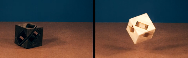
MIT’s Computer Science and Artificial Intelligence Laboratory, CSAIL, put out a paper recently about an interesting advance in 3D printing. Naturally, being the computer science and AI lab the paper had a robotic bend to it. In summary, they can 3D print a robot with a rubber skin of arbitrarily varying stiffness. The end goal? Shock absorbing skin!
They modified an Objet printer to print simultaneously using three materials. One is a UV curing solid. One is a UV curing rubber, and the other is an unreactive liquid. By carefully depositing these in a pattern they can print a material with any property they like. In doing so they have been able to print mono body robots that, simply put, crash into the ground better. There are other uses of course, from joints to sensor housings. There’s more in the paper.
We’re not sure how this compares to the Objet’s existing ability to mix flexible resins together to produce different Shore ratings. Likely this offers more seamless transitions and a wider range of material properties. From the paper it also appears to dampen better than the alternatives. Either way, it’s an interesting advance and approach. We wonder if it’s possible to reproduce on a larger scale with FDM.
At my university, we were all forced to take a class called Engineering 101. Weirdly, we could take it at any point in our careers at the school. So I put it off for more interesting classes until I was forced to take it in one of my final years. It was a mess of a class and never quite seemed to build up to a theme or a message. However, every third class or so they’d dredge up a veritable fossil from their ranks of graduates. These greybeards would sit at the front of the class and tell us about incredible things. It was worth the other two days of nondescript rambling by whichever engineering professor drew the short straw for one of their TAs.
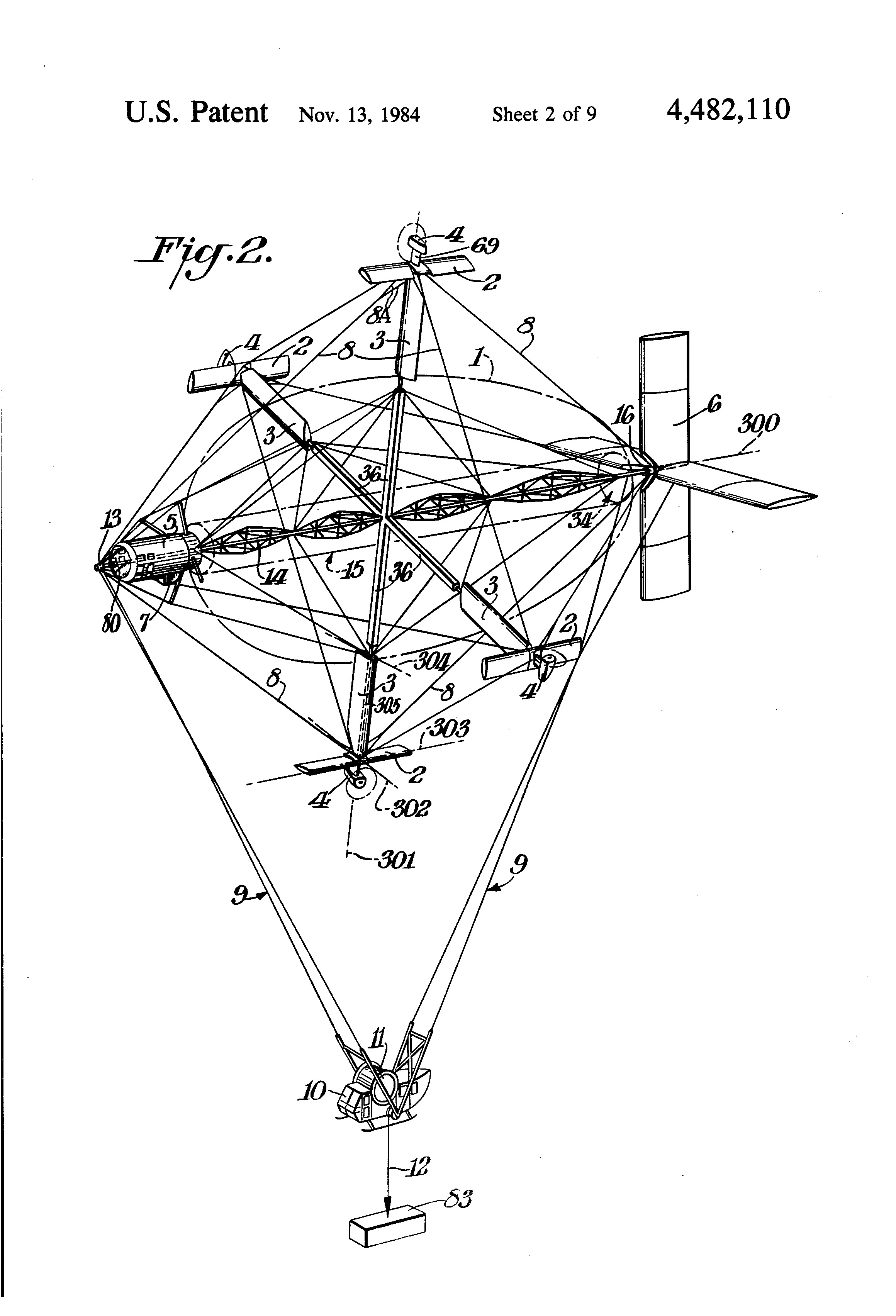
The patent drawing.
One greybeard in particular had a long career in America’s unending string of, “Build cool stuff to help us make bad guys more deader,” projects. He worked on stealth boats, airplanes with wings that flex, and all sorts of incredibly cool stuff. I forgot about the details of those, but the one that stuck with me was the Cyclocrane. It had a ton of issues, and as the final verdict from a DARPA higher-up with a military rank was that it, “looked dumb as shit” (or so the greybeard informed us).
A Cyclo-What?
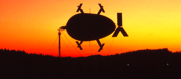
The Cyclocrane was a hybrid airship. Part aerodynamic and part aerostatic, or more simply put, a big balloon with an airplane glued on. Airships are great because they have a constant static lift, in nearly all cases this is buoyancy from a gas that is lighter than air. The ship doesn’t “weigh” anything, so the only energy that needs to be expended is the energy needed to move it through the air to wherever it needs to go. Airplanes are also great, but need to spend fuel to lift themselves off the ground as well as point in the right direction. Helicopters are cool because they make so much noise that the earth can’t stand to be near them, providing lift. Now, there’s a huge list of pros and cons for each and there’s certainly a reason we use airplanes and not dirigibles for most tasks. The Cyclocrane was designed to fit an interesting use case somewhere in the middle.
In the logging industry they often use helicopters to lift machinery in and out of remote areas. However, lifting two tons with a helicopter is not the most efficient way to go about it. Airplanes are way more efficient but there’s an obvious problem with that. They only reach their peak efficiency at the speed and direction for which their various aerodynamic surfaces have been tuned. Also worth noting that they’re fairly bad at hovering. It’s really hard to lift a basket of chainsaws out of the woods safely when the vehicle doing it is moving at 120mph.
The cyclocrane wanted all the efficiency of a dirigible with the maneuverability of a helicopter. It wanted to be able to use the effective lifting design of an airplane wing too. It wanted to have and eat three cakes. It nearly did.
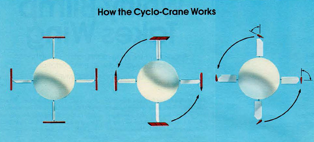
A Spinning Balloon with Wings
Four wings stick out of a rotating balloon. The balloon provides half of the aerostatic lift needed to hold the plane and the cargo up in the air. The weight is tied to the static ends of the balloon and hang via cables below the construction. The clever part is the four equidistant wings sticking out at right angles from the center of the ship. At the tip of each wing is a construction made up of a propellor and a second wing. Using this array of aerofoils and engines it was possible for the cyclocrane to spin its core at 13 revolutions per minute. This produced an airspeed of 60 mph for the wings. Which resulted in a ton of lift when the wings were angled back and forth in a cyclical pattern. All the while, the ship remaining perfectly stationary.
Now the ship had lots of problems. It was too heavy. It needed bigger engines. It was slow. It looked goofy. It didn’t like strong winds. The biggest problem was a lack of funding. It’s possible that the cyclocrane could have changed a few industries if its designers had been able to keep testing it. In the end it had a mere seven hours of flying time logged with its only commercial contract before the money was gone.
However! There may be some opportunity for hackers here. If you want to make the quadcopter nerds feel a slight sting of jealousy, a cyclocrane is the project for you. A heavy lift robot that’s potentially more efficient than a balloon with fans on it is pretty neat. There’s a bit of reverse engineering to be done before a true performance statement can be made. If nothing else. It’s just a cool piece of aerospace history that reminds us of the comforting fact that we haven’t even come close to inventing it all yet.
If you’d like to learn more there’s a ton of information and pictures on one of the engineer’s website. Naturally wikipedia has a bit to say. There’s also decent documentary on youtube, viewable below.
 Fail of the Week is a Hackaday column which celebrates failure as a learning tool. Help keep the fun rolling by writing about your own failures and