Pool Noodle Robot Shines A Light On The Pros And Cons Of Soft Robots

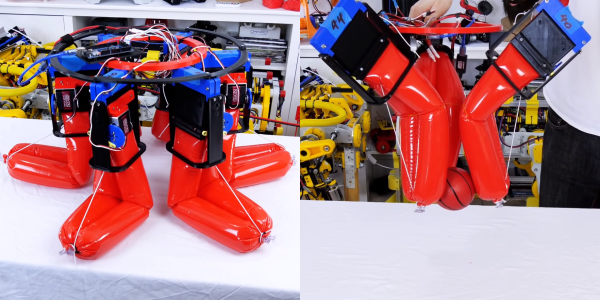
[James Bruton]’s impressive portfolio of robots has always used conventional rigid components, so he decided to take a bit of a detour and try his hand at a soft robot. Using a couple of few inflatable pool noodles for quick prototyping, his experiments quickly showed some of the strengths and weaknesses of soft robots.

Most of the soft robots we see require an external air source to inflate cells in the robot and make the limbs actuate. Taking inspiration from a recent Stanford research project, [James] decided to take an alternative approach, using partially inflated tubes and squeezing them in one section to make the other sections more rigid. He bought a couple of cheap pool noodles and experimented with different methods of turning them into actuators. The approach he settled on was a pair of noodles tied together side by side, and then folded in half by an elastic cord. As one end is squeezed by a servo bellows, the internal pressure overcomes the tension from the elastic cord, and the “elbow” straightens out.

[James] tested various arrangements of these limbs to build a working hexapod robot but to no avail. The simple actuating mechanism was simply too heavy, and could just lift itself slightly. This highlighted a common theme in almost all the soft pneumatic robots we’ve seen: they carry very little weight and are always tethered to an external air supply. The combination of stretchy materials and relatively low pressure compressed air can only handle small loads, at least in Earth gravity and above water. Continue reading “Pool Noodle Robot Shines A Light On The Pros And Cons Of Soft Robots”

Electric Airboat For Getting You Across Thin Ice

Even with all the technological progress civilization has made, weather and seasons still have a major impact on our lives. [John de Hosson] owns a cabin on an island in a Swedish lake, and reaching it involves crossing 500 m of water. In summer this is done with a conventional boat, and in winter they can simply walk across the thick ice, but neither of these is an option on thin ice in the spring or fall. To solve this [John] built an electric airboat, and it looks like a ton of fun in the video after the break

The construction is simple but functional. A 3.3 m flat-bottomed aluminum boat has used a base, and an aluminum frame was bolted on for the motor and propeller. The motor is an 18 kW brushless motor, with a 160 cm/63-inch carbon fiber propeller. Power comes via a 1000 A ESC from a 100V 3.7 kWh Lipo pack mounted in a plastic box. Steering is very similar to a normal airboat, with a pair of air rudders behind the propeller, controlled by a steering lever next to the driver’s seat. The throttle is an RC controller with the receiver wired to the ESC.

Performance is excellent, and it accelerates well on ice and slush, even with two people on board. [John] still plans to make several improvements, with a full safety cage around the propeller being at the top of the list. He is also concerned that it will capsize on the water with the narrow hull, so a wider hull is planned. [John] has already bought a large steering servo to allow full remote control for moving cargo, with the addition of an FPV system. We would also add an emergency kill switch and waterproofing for the electronics to the list of upgrades. It looks as though the battery box is already removable, which is perfect for getting it out of the cold when not in use.

Continue reading “Electric Airboat For Getting You Across Thin Ice”

Demonstrating The Mars Rover Pendulum Problem With A Drone On Earth

The sky crane system used on the Perseverance and Curiosity Mars rovers is a challenging control system problem that piqued [Nicholas Rehm]’s curiosity. Constrained to Earth, he decided to investigate the problem using a drone and a rock.

The setup and the tests are simple, but clearly illustrate the problem faced by NASA engineers. [Nicholas] attached a winch mechanism to the bottom of a racing-type quadcopter, and tied a mass to the end of the winch line. At first, he built a foam model of the rover, but it proved to be unstable in the wake of the quadcopter’s propellers, so he used a rock instead. The tests start with the quadcopter taking off with the rock completely retracted, which is then slowly lowered in flight until it reaches the end of the line and drops free. As soon as the rock was lowered, it started swinging like a pendulum, which only got worse as the line got longer. [Nicholas] attempted to reduce the oscillations with manual control inputs, but this only made it worse. The quadcopter is also running [Nicholas]’s own dRehmFlight flight controller that handles stabilization, but it does not account for the swinging mass.

[Nicholas] goes into detail on the dynamics of this system, which is basically a two-body pendulum. The challenges of accurately controlling a two-body pendulum are one of the main reasons the sky crane concept was shelved when first proposed in 1999. Any horizontal movement of either the drone or the rock exerts a force on the other body and will cause a pendulum motion to start, which the control system will not be able to recover from if it does not account for it. The real sky crane probably has some sort of angle sensing on the tether which can be used to compensate for any motion of the suspended rover. Continue reading “Demonstrating The Mars Rover Pendulum Problem With A Drone On Earth”

DIY USB-C Touch Monitor Is All Polished Brass

We’ve known for a while that you can buy interface boards to turn old laptop screens into standalone monitors, but complete sets with 4K panels and control boards are also now becoming widely available on sites like eBay and AliExpress, and prices are dropping. These sets are also available with low-profile connectors like micro HDMI and USB-C, which allow for some very compact builds.

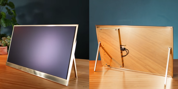
[Matt] from [DIY Perks] used one of these sets to build a slimline USB-C monitor with a brass enclosure. Video after the break. The enclosure consists of brass sheets and U-channel pieces soldered and screwed together. There is quite a bit of residue and discoloration after soldering, but this was removed with a bit of sanding and polishing. A pair of adjustable legs were added to allow it to stand on its own, and an additional chamber on the back holds the control board, an old smartphone battery, and a battery protection circuit. [Matt] also added a pair of removable speakers, which are sealed speaker units covered in brass mesh and plate.

We’ve covered several DIY monitor builds over the years, and they are perfect as an additional monitor for a laptop, or for pairing with the Raspberry Pi 400 with its integrated keyboard. We really [Matt]’s builds, which include a smartphone-based 4K projector, and a very effective cooling system for an expensive DSLR camera. Continue reading “DIY USB-C Touch Monitor Is All Polished Brass”

Robotic Pool Cue Can Be Your Friend Or Your Foe

In his everlasting quest to replace physical skill with technology, [Shane] of [Stuff Made Here] has taken aim at the game of eight-ball pool. Using a combination of computer vision and mechatronics, he created a robotic pool system that can allow a physical game of pool over the internet, or just beat human players. See the video after the break.

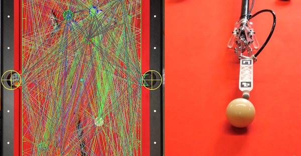
Making a good pool shot requires three discrete steps. First, you need to identify the best shot, then figure out how exactly to strike the balls to achieve the desired results, and finally physically execute the shot accurately. [Shane’s] goal was to automate all these steps. For the physical part, he built a pool cue with a robotic tip which only requires the user to place in approximately the right position, while a pneumatic piston mounted on a Stewart platform does the rest. A Stewart platform is a triangular plate mounted with six reciprocating rods, which gives it the required freedom of motion. The rods’ bases are attached to a set of cranks actuated by tension cables pulled by servos mounted at the rear-end of the cue. An adjustable air system allows the power of the shot to be adjusted as required.

A camera mounted is mounted over the table and connected to computer vision software to gather the required position information. Fiducials on the corners of the table and the cue tip allow the position of the pockets, balls, and cue to be accurately determined, and theoretically should allow the robot to take the perfect shot. Getting this to work in reality quickly turned into a very frustrating experience. After many hours of debugging, [Shane] tracked the error to a tiny forgotten test function that was introducing 5-10 mm of position error, and 2 of the six servos in the cue not performing up to spec. To determine the vertical positioning of the cue, an IMU and fixed height foot were added. [Shane] also added an overhead projector to overlay all required information directly on the table. Continue reading “Robotic Pool Cue Can Be Your Friend Or Your Foe”

Deleting The Camshafts From A Miata Engine

The idea of camless automotive engines has been around for a while but so far has been limited to prototypes and hypercars. [Wesley Kagan] has been working on a DIY version for a while, and successfully converted a Mazda Miata to a camless valve system. See the videos after the break.

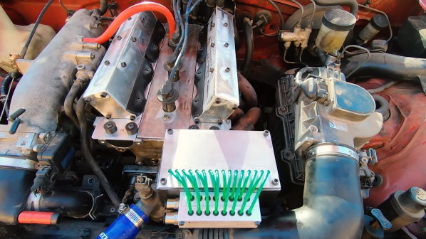
There have been many R&D projects by car manufacturers to eliminate camshafts in order to achieve independent valve timing, but the technology has only seen commercial use on Koenigsegg hypercars. [Wesley] started this adventure on a cheap single cylinder Harbor Freight engine, and proved the basic concept, so he decided to move up to an actual car. He first sourced a junkyard engine head to convert, and use as a drop-in replacement for the head on the complete project car. An off-the-shelf double-acting pneumatic cylinder is mounted over each valve and connected to the valve stem with a custom adaptor. The double-acting cylinder allows the valve to be both opened and closed with air pressure, but [Wesley] still added the light-weight return spring to keep the valve closed if there is any problem with the pneumatic system.

The controller is an Arduino, and it receives a timing signal from a factory crankshaft and operates the pneumatic solenoid valves via MOSFETs. After mounting the new head and control box into the Miata, it took a couple of days of tuning to get the engine running smoothly. Initial tests were done using the compressor in his garage, but this was replaced with a small compressor and air tank mounted in the Miata’s boot for the driving tests.

Although the pneumatic system works well for short test drives, the compressor is quite noisy and adds a couple of points of failure. [Wesley] is also working on a solenoid actuated system, which would require a lot more current from the battery and alternator, but he believes it’s a better long-term solution compared to compressed air. However, he is still struggling to find solenoids with the required specifications. Continue reading “Deleting The Camshafts From A Miata Engine”

Pelton Turbine Development For An Air Powered Model Helicopter

[Tom Stanton] has been messing around with compressed air power for a few years now, and most of his work focused on piston engines. He likes using 2-liter soda bottles as lightweight tanks but their capacity is limited, so the nozzle can be a maximum of 1 mm in diameter if he wants to produce thrust for 30 seconds or longer using a turbine. Pelton turbines have been in use for a long time, especially for hydroelectric systems, and they use small diameter nozzles, so he decided to experiment with a pneumatic Pelton turbine. (Video, embedded below.)

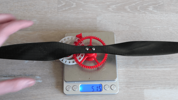
Pelton wheels are water wheels with specially designed buckets to efficiently extract energy from a high-velocity jet of water. [Tom] 3D printed several geared Pelton turbines and started doing bench tests with a propeller and a load cell to gather empirical data. With the help of high-speed video of the tests, he quickly realized that the turbine efficiency is highly dependent on the load. If the load is too small or too large, the moving air will not come to a complete standstill, and energy will be wasted. [Tom] also suspected that some moving air was escaping from the bucket, so he created a version that enclosed the buckets with a ring on the outer perimeter, which increased the peak thrust output by 65%. Compared to his diaphragm air engine design, the peak thrust is higher, but the overall efficiency is less. [Tom] believes there is still room for improvement, so he plans to continue working on the Pelton turbine concept, with the hopes of building an air-powered model helicopter that can lift off. Continue reading “Pelton Turbine Development For An Air Powered Model Helicopter”