Jackpot!: The Trials And Tribulations Of Turning A Slot Machine Into An ATM

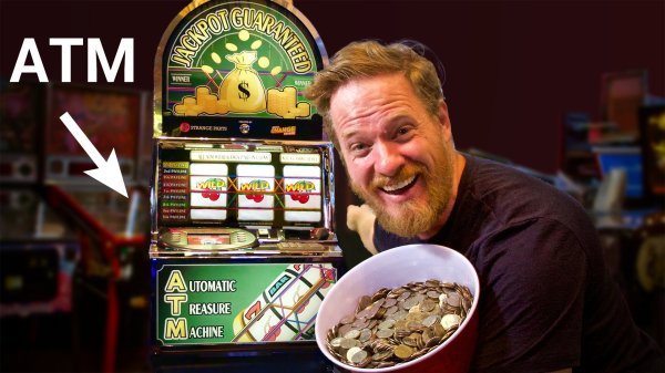
Have you ever wished that slot machines dispensed money as easily as an ATM? Well so did [Scotty Allen] from Strange Parts, so in collaboration with his friend [Matt] decided to combine the two. After a four-month journey fraught with magic smoke and frustration, they managed to build a fully functional ATM slot machine.

The basic idea is that you insert your card and enter your pin like on a normal ATM, select your winning amount, and pull the lever. This sets wheels spinning, which come to a stop with three-of-a-kind every time, and you win your own money as a bucket load of coins with all the accompanying fanfare. The project took way longer than [Scotty] expected, and he ended up missing his original deadline to show off the machine at DEF CON.

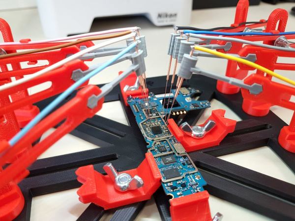
They started with an old broken Japanese slot machine, and replaced the control board with an Arduino Due after a lot of reverse engineering and hacking. [Scotty] did a cool video just on getting the original vacuum fluorescent display working. Integrating the ATM parts proved to be the biggest challenge, with number of very expensive parts releasing their magic smoke or getting bricked in the process. [Scotty] came up with an ingeniously simple hack to interface the ATM hardware with the Arduino. The cash note dispenser uses multiple sensors to detect if there are notes loaded and if one is successfully dispensed. These were spoofed by the Arduino, which controls two coin hoppers instead to dispense appropriate amount of quarters or pennies. The build was rounded off with some very neat custom graphics on the glass panels, and the machine was finally showed off at a local arcade.

This was an awesome project, and we can appreciate the fact that [Scotty] made no attempt to hide the real emotional roller coaster that anyone who has worked on a large project knows, but is rarely documented in logs. [Scotty] has made a name for himself by building his own iPhone from parts and touring Shenzhen’s many factories. Check out the videos after the break Continue reading “Jackpot!: The Trials And Tribulations Of Turning A Slot Machine Into An ATM”

Needling Your Projects: 3D Printed PCB Probing Jig Uses Accupuncture Needles

Trying to probe a modern electronic circuit with tiny SMD components, without letting the magic smoke escape in the process, can be quite a challenge. Especially since we hackers have not yet developed the number of appendages required to hold 3 different probes in place while operating both an oscilloscope and a computer. [Giuseppe Finizia] solved this problem with a 3D printed PCB probing jig that uses acupuncture needles.

As part of [Giuseppe] day job as an engineer at an electronic forensics laboratory, he does technical investigations on seized devices, which involves quite a bit of probing. The jig consists of a base plate with slots in which PCB holders of various configurations slide to hold all shapes and sizes of PCBs. Around the circumference of the plate there are multiple positions for adjustable probing “cranes”, each of which hold an acupuncture needle that is crimped or soldered to a wire. Each needle holder has a bit of flex which allows it to maintain downward pressure for a positive connection.

Making one-off tools and jigs is arguably one of the best applications for 3D printing, of which this is a perfect example. You can of course point solder wires or use test hooks if you have something to grab onto, but for easily probing multiple point on any PCB, this looks like a damn good solution. If you’re trying to trace a single signal, a precision pantograph might be your friend, or you can add a foot switch to your oscilloscope for quickly checking a circuit by hand.

[Jonathon Oxer] from the YouTube channel SuperHouse did a very nice video on the jig and made some small modifications. Check out the video after the break.

DIY Electrolysis Tank: Removing Rust While You Sleep

Anyone who’s done a bit of metalworking will know how quickly your stockpile will pick up a coating of rust with even just a bit of humidity. While welding requires only a bit of wire brushing at the joint areas, cleaning a large frame for paint is a completely different story. The projects [Make it Extreme] gets himself into tend to involve a lot of steel, so he built his own electrolysis tank for rust removal.

Electrolytic rust removal involves placing the piece of steel to be cleaned into an alkaline electrolyte solution (water and washing soda) with a sacrificial steel anode and connecting a low voltage DC supply over the two pieces. [Make it Extreme] started with an old plastic container, around which he built a very neat trolley frame. He obviously put some thought into how the tank will be cleaned, since it can be removed by unscrewing six bolts and removing the top part of the frame.

The high current, low voltage power supply that is required for the process was built using an old microwave transformer. The secondary coil is removed and replaced with coil of thick insulated wire, to convert it into a step down transformer. After the rewinding the transformer outputs about 13 VAC, which is then run through beefy bridge rectifier modules to get a DC current. A custom machined copper bolt terminal is mounted through the side of the tank to attach the sacrificial anode plate to the positive lead of the power supply, while the negative lead is clamped to the rusty steel to be cleaned.

[Make it Extreme]’s projects never get old, with everything from rideable tank tracks to rotary electric guns. Check out the video after the break to see the build and an impressive demo. Continue reading “DIY Electrolysis Tank: Removing Rust While You Sleep”

Making A Robotic Dog Better By Adding Springiness Without Springs

Getting a legged robot to stay upright, especially a quadruped or biped, can be a challenging undertaking. To experiment with different approaches, [James Bruton] built robot dog test platform and is playing with “dynamic compliant simulated springs“, or in other words, using the motors to act as though they were springs and dampers..

When robotic legs are kept stiff, they tend to reduce the stability of the platform due to the sudden erratic movements of the robot, especially on uneven surfaces. With a back drivable joint arrangement, [James] is using limited holding current on the motor, and the position of the motor shaft is monitored using an encoder. When a leg experiences a resisting force, with will have some “give” and then the motor will return it to it’s intended position more slowly. Using a IMU on top of the robot, it can detect when it start leaning to a side, and then temporarily soften the other side to balance the robot.

This is quite a common technique in legged robots, but [James] does an excellent job of explaining just how it works. He hopes to use the lessons learned from the test platform to improve or redesign his already impressive OpenDog.

We’ve seen a number of quadruped robots on Hackaday recently. Including Boston Dynamics’ very expensive Spot as well as a low cost robot dog that giving its big brothers a run for their money, and doing some back flips in the process. Check out James’ video after the break. Continue reading “Making A Robotic Dog Better By Adding Springiness Without Springs”

Tiny Drones Navigate Like Real Bugs

When it comes to robotic navigation, the usual approach is to go as technically advanced and “smart” as possible. Yet the most successful lifeforms that we know of follow a completely different approach. With limited senses and cognitive abilities, the success of invertebrates like ants and honeybees lie in cooperation in large numbers. A joint team of researchers from TU Delft, University of Liverpool and Radboud University of Nijmegen, decided to try this approach and experimented with a simple navigation technique to allow a swarm of tiny flying robots to explore an unknown environment.

The drones used were of-the-shelf Crazyflie 2.0 micro quadcopters with add-on boards. Sensors consisted of it’s onboard IMU, simple range finding sensors on a Multi-ranger deck for obstacle detection, and a down pointing optical flow sensor, on a Flow deck, to keep track of the distance travelled.  To navigate, the drones used a “swarm gradient bug algorithm” (SGBA).  Each drone in has different preferred direction of travel from takeoff. When an obstacle encountered, it follows the contour of the obstacle, and then continues  in the preferred direction once the path is clear.  When the battery drops to 60%, it returns to a wireless homing beacon. While this technique might not be the most efficient, it has the major advantage of being “lightweight” enough to implement on a cheap microcontroller, an STM32F4 in this case. The full research article is available for free, and is a treasure trove of information.

The main application researchers have in mind is for search and rescue. A swarm of drones can explore an unstable or dangerous area, and identify key areas to focus rescue efforts on.  This can drastically reduce wasted time and risk to rescue workers. It is always cool to see complex problems being solved with simple solution, and we are keen to see where things go. Check out the video after the break. Continue reading “Tiny Drones Navigate Like Real Bugs”

Autonomous Air Boat Vs Lake Washington

Autonomous vehicles make a regular appearance around here, as does [Daniel Riley] aka [rctestflight]. His fascination with building long-endurance autonomous vehicles continues, and this time he built an autonomous air boat.

This craft incorporates a lot of the lessons learnt from his autonomous boat that used a plastic food container. One of the biggest issues was the submerged propellers kept getting tangled in weeds. This led [Daniel] to move his props above water, sacrificing some efficiency for reliability, and turning it into an air boat. The boat itself is catamaran design with separate 3D printed hulls connected by carbon fibre tubes. As with the tupperware boat, autonomous control is done by the open source Ardupilot software.

During testing [Daniel] had another run in with his old arch-nemesis, seaweed. It turns out the sharp vertical bow is a nice edge for weeds to hook on to, create drag, and screw up the craft’s control. [Daniel]’s workaround involved moving the big batteries to the rear, causing the bows lift almost completely out of the water.

With a long endurance in mind right from the start of the project, [Daniel] put it to the test with a 13 km mission on Lake Washington very early one morning. For most of the mission the boat was completely on its own, with [Daniel] stopping at various points along the lake shore to check on its progress. Everything went smoothly until 10 km into the mission when the telemetry showed it slowing down and angling off course, after which is started going in circles. Lucky for Daniel he was offered a kayak by a lakeside resident, and he managed to recover the half sunken vessel. He suspects the cause of the failure was a slowly leaking hull. [Daniel] is already working on the next version, and were looking forward to seeing what he comes up with. Check out the video after the break. Continue reading “Autonomous Air Boat Vs Lake Washington”

Traffic Updates On The Seven Seas: Open Source Chart Plotter Using A Raspberry Pi

As the Raspberry Pi in its various forms continues to flow into the wild by the thousands, it’s interesting to see its user base expand outside beyond the hacker communities. One group of people who’ve also started taking a liking to it is sailing enthusiasts. [James Conger] is one such sailor, and he built his own AIS enabled chart plotter for a fraction of the price of comparable commercial units.

AIS transponders in the Mediterranean. VesselFinder

Automatic Identification System (AIS) is a GPS tracking system that uses transponders to transmit a ship’s position data to other ships or receiver stations in an area. This is used for collision avoidance and by authorities (and hobbyists) to keep an eye on shipping traffic, and allow for stricken vessels to be found easily. [James]’ DIY chart plotter overlays the received AIS data over marine charts on a nice big display. A Raspberry Pi 3B+, AIS Receiver Hat, USB GPS dongle and a makes up the core of the system. The entire setup cost about $350. The Pi runs OpenCPN, an open source chart plotter and navigation software package that [John] says is rivals most commercial software. As most Pi users will know the SD card is often a weak link, so it’s probably worth having a backup SD card with all the software already installed just in case it fails during a voyage.

We’ve seen AIS receiver stations built using the RTL-SDR, as well as a number of projects around the AIS equivalent in aviation, ADS-B. Check out [John]’s video after the break. Continue reading “Traffic Updates On The Seven Seas: Open Source Chart Plotter Using A Raspberry Pi”