The Most Ornate Birdbath You’ve Ever Seen

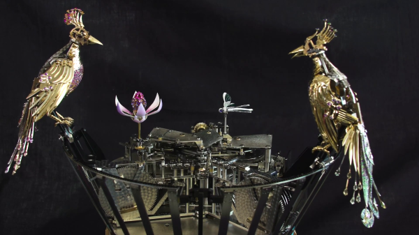
When one thinks of art, a birdbath may not be the first thing that comes to mind. However, there is no denying that the La Fontaine aux Oiseaux (The Bird Fountain) is a true work of art. This automaton, created by automaton maker [François Junod] in collaboration with 20 different workshops and craftsmen, represents thousands of hours of work and boasts a complex beauty that is both visible and hidden.The finished Bird Fountain, with all it's jewel encrusted exterior pieces

Commissioned by the Van Cleef & Arpels jewelry company, this purely mechanical display piece features a pair of jewel-encrusted birds that perform a little routine around the edge of the bath every hour. All the birds’ appendages move while bird song is added with the help of a whistle and bellows. The “water” is also mechanized, with a series of metal plates moving together to create ripple effects, while a water lily opens and closes and a dragonfly flutters above the surface.

The overall effect of this ridiculously over-the-top mechanical art piece is absolutely mesmerizing. Even if the bejeweled exterior isn’t quite your style, you can still appreciate its intricate workings thanks the video after the break giving us a peek at the development.

We’ve featured some of [François]’ other work before, which is equally impressive and displays the mechanics in all it’s glory. If you want to try your hand at making automatons, 3D printing is the perfect way to get started.

Continue reading “The Most Ornate Birdbath You’ve Ever Seen”

A Simple Guide To Cams

With the availability of precision controllable actuators, it’s easy to overlook the simple but versatile mechanisms that got us here. In the video after the break, [Teaching Tech] explores the basics of cams and how to use them in your projects.

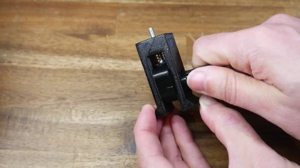
Cams are used to convert rotation into linear motion, and are probably best known for their use in engines and locking mechanisms. [Teaching Tech] first goes over the basic design and terminology in CAD, and demonstrates it’s use with a cam follower, locking mechanism, cam plate, and a knob that snaps to predefined positions. Of course a cam shape is not limited to a single lobe, but can have multiple lobes of various heights to create different motion patterns.

Cams are especially useful when you need to operate multiple mechanisms from a single input drive, as [Teaching Tech] demonstrates with the 3D printed automaton of a polar bear attempting to swipe a seal. We’ve also seen cams on a mechanical 7-segment display, and they were used to safely fire machine guns through aircraft propellers up to the 1950’s.

So next time you’re thinking adding another actuator to a project, take a moment to consider if a cheap and simple cam could do the job.

Continue reading “A Simple Guide To Cams”

Hackaday Prize 2023: Low Cost Braille Embosser From 3D Printer Parts

The limited availability of texts transcribed to Braille and the required embossing equipment is a challenge world wide, but especially in poorer countries. To alleviate this problem, a team makers from in Cameroon have been developing BrailleRAP, an open source Braille embosser.

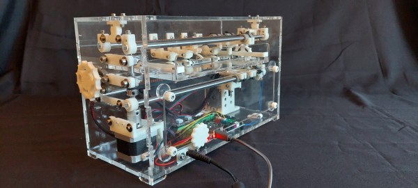
BrailleRAP is built built using commonly available 3D printer components, printed parts, and a laser-cut acrylic or wood frame. Paper is fed between a pair of carriages, the bottom one punching dots with a solenoid while the other acts as the anvil. Sheets of paper are fed in one or two at a time with stepper controlled rollers to control the position. At a cost of about $250, it is about a tenth of the price of the cheapest commercial solution, and the team have created excellent documentation so anyone can build it.

BrailleRAP was inspired by BRAIGO, another Hackaday-featured embosser assembled LEGO Mindstorm parts. We also featured another simple, but ingenious handheld embosser for portable use.

Continue reading “Hackaday Prize 2023: Low Cost Braille Embosser From 3D Printer Parts”

DIY 3D Printed Rain Gauge Connects To Home Assistant

Measuring local rainfall has real practical uses, especially in agriculture, but most of us will have to admit that it’s at least partly about drawing cool graphs on a screen. Whatever your motivation, you can build this open source electronic rain gauge designed by [Sebastian] of Smart Solutions for Home, and integrate it with Home Assistant.

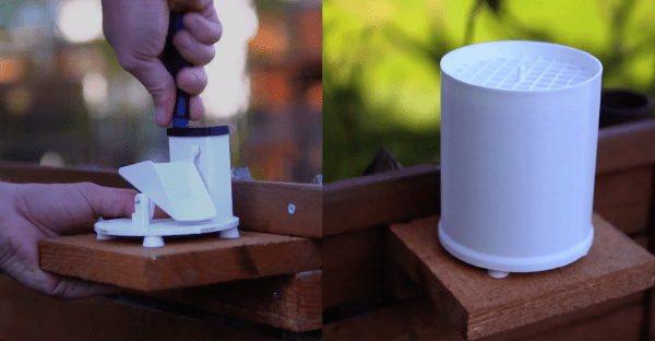
This 3D printed rain gauge is of the ubiquitous tipping bucket type and uses a magnet and hall effect sensor to detect every time the bucket tips out. The sensor is soldered to a custom PCB with ESP32 configured using ESP Home. By keeping it in deep sleep most of the time and only waking up when the tip of the bucket, [Sebastian] estimates it can run about a year on four AA batteries, depending on rainfall. The hinge mechanism is adjustable to ensure that both buckets will tip with the same volume of water.

FDM 3D printed enclosures are not known for being waterproof, so [Sebastian] coated the PCB with varnish to protect it from moisture. This worked well enough that he could leave it running in a bowl of water for a few hours without any ill effects. The end result looks good and should be able to handle the outdoors for a long time.

Building a weather station is a popular DIY project. Some of the interesting varieties we’ve seen are powered by supercapacitors, show readings on antique analog dials and convert parking distance sensor kit into a wind gauge.

Continue reading “DIY 3D Printed Rain Gauge Connects To Home Assistant”

Automate Handwritten Postcards With Robots

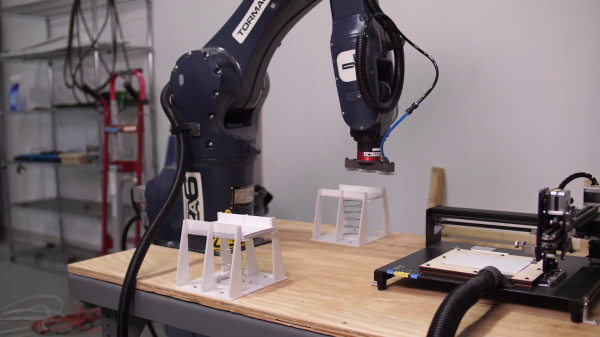
As someone notorious for not doing things the old-fashioned manual way, we’re not sure by [Shane] of Stuff Made Here was thinking when he promised to send out a few hundred handwritten letters. Predictably he built an automated production line for the task. Video after the break.

With “handwritten” and “automated” not being particularly compatible, [Shane] set out to create a robot to create believable handwritten letters, which is significantly harder than it may seem at first glance. It turns out that turning your handwriting into a font is too consistent to be believable, which led down the rabbit of generated handwriting. [Shane] first spend a ridiculous amount of time trying to implement a machine learning model for the task, only to find there’s already an open source library good enough to fool a forensic handwriting expert.

On the robot side, [Shane] used a pen plotter from Amazon that’s it’s actually cheaper than building one from scratch. With the “handwriting” taken care of, [Shane] set up an automated loading system with the industrial robot arm he also used for his CNC chainsaw. The feeders for the empty and full postcards are 3D printed with a spring-loaded mechanism to keep the top card at the same height all the time.

Although this project contained less custom hardware and software than [Shane’s] other projects, it served as an excellent reminder that it’s unnecessary to reinvent the wheel when building a car. It’s easy to get caught up in the small details of a project that don’t matter much in the final implementation and usage.

Continue reading “Automate Handwritten Postcards With Robots”

The Fascinating Evolution Of Micromouse

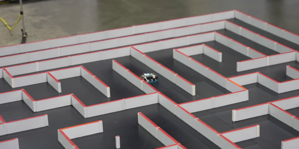
You would think there are only so many ways for a robotic mouse to run a maze, but in its almost 50 year history, competitors in Micromouse events have repeatedly proven this assumption false. In the video after the break, [Veritasium] takes us on a fascinating journey through the development of Micromouse competition robots.

The goal of Micromouse is simple: Get to the destination square (center) of a maze in the shortest time. Competitors are not allowed to update the programming of their vehicles once the layout is revealed at the start of an event. Over the years, there have been several innovations that might seem obvious now but were groundbreaking at the time.

The most obvious first challenge is finding the maze’s center. Simple wall following in the first event in 1977 has developed into variations of the “flood fill” algorithm. Initially, all robots stopped before turning a corner until someone realized that you could cut corners at 45° and move diagonally if the robot is narrow enough. The shortest path is not always the fastest since cornering loses a lot of speed, so it’s sometimes possible to improve time by picking a slightly longer router with fewer corners.

More speed is only good if you can keep control, so many robots now incorporate fans to suck them down, increasing traction. This has led to speeds as high as 7 meters/second and cornering forces of up to 6 G. Even specks of dust can cause loss of control, so all competitors use tape to clean their wheels before a run. Many winning runs are now under 10 seconds, which require many design iterations to increase controllable speed and reduce weight.

All these innovations started as experiments, and the beauty of Microhouse lies in its accessibility. It doesn’t require much of a budget to get started, and the technical barrier to entry is lower than ever. We’ve looked at another Micromouse design before. Even if they aren’t micromice, we can’t get enough of tiny robots.

Continue reading “The Fascinating Evolution Of Micromouse”

3D Printing Bores Without Support

If you’ve done even a small amount of 3D printing, you probably ran into the challenge of printing a small hole on top of a larger hole. The conventional solution is just to add support, but in the video after the break, [Angus] of Maker’s Muse demonstrates an alternative solution you can implement in CAD, without having to do manual post-processing.

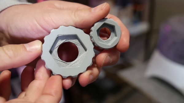
This is a common problem when you have a countersink feature for a bolt head or captured nut on the bottom of the part. [Angus] first demonstrates some other techniques, including printing the bore over empty space, adding a sacrificial bridge, and making the overhang 45°. Each of these work but have some trade-offs. The proposed solution is what [Angus] calls sequential overhangs. It involves bridging the sides of the open space in steps to create supporting edges onto which the bore perimeter can print. It starts with 2 or 3 bridging layers to create a rectangle the same width as the bore, and then a second set of bridges at 90° to turn the opening into a square. For smaller holes this should create enough of a support to start the bore perimeter, but for larger holes three sets of bridges at 60° offsets might be needed.

[Angus] does not claim to have invented the technique but states he borrowed the idea from parts printed by Prusa Research for their popular line of 3D printers. One of the comments on the [Maker’s Muse] video referenced a 2014 blog post by [nophead] showing the same approach. Regardless of the idea’s lineage, it’s a great addition to anyone’s 3D printing design toolbox.
Continue reading “3D Printing Bores Without Support”