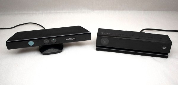
The tale of the Microsoft Xbox Kinect is one of those sad situations where a great product was used in an application that turned out to be a bit of a flop and was discontinued because of it, despite its usefulness in other areas. This article from the Guardian is a quick read on how this handy depth camera has found other uses in somewhat niche areas, with not a computer game in sight.
It’s rather obvious that a camera that can generate a 3D depth map, in parallel with a 2D reference image, could have many applications beyond gaming, especially in the hands of us hackers. Potential uses include autonomous roving robots, 3D scanning, and complex user interfaces—there are endless possibilities. Artists producing interactive art exhibits would sit firmly in that last category, with the Kinect used in countless installations worldwide.
Apparently, the Kinect also has quite the following in ghost-hunting circles, which as many a dubious TV show would demonstrate, seem almost entirely filmed under IR light conditions. The Kinect’s IR-based structured light system is well-suited for these environments. Since its processing core runs a machine learning application specifically trained to track human figures, it’s no surprise that the device can pick up those invisible, pesky spirits hiding in the noise. Anyway, all of these applications depend on the used-market supply of Kinect devices, over a decade old, that can be found online and in car boot sales, which means one day, the Kinect really will die off, only to be replaced with specialist devices that cost orders of magnitude more to acquire.
In the unlikely event you’ve not encountered non-gaming applications for the Kinect, here’s an old project to scan an entire room to get you started. Just to be perverse, here’s a gaming application that Microsoft didn’t think of, and to round out, the bad news that Microsoft has really has abandoned the product.


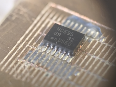 prevent the tool from chattering across the surface of the FR4 blank. Controlling and maintaining the rake angle was a critical parameter here. [Zach] actually took an additional step, which we likely wouldn’t have thought of, to have some copper blanks pre-fabricated to the required size and finished with an ENIG coating. It’s definitely a smart move!


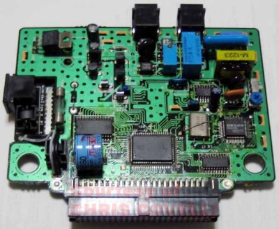 removable cartridge, complete with a BASIC interpreter and a collection of graphical editor tools for game creation.
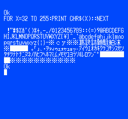 even a map editor. We think inputting BASIC code via a gamepad would get old fast, but it would work a little better for graphical editing.


