Android Doorbell Notifier

Breadboarded circuit to detect when doorbell rings

It’s always unfortunate to find a FedEx tag on your door saying you missed a delivery; especially when you were home the whole time. After having this problem a few times [Lee] decided to rig up a doorbell notifier for his Android phone.

[Lee]’s doorbell uses a 10 VAC supply to ring a chime. To reduce modifications to the doorbell, he added an integrated rectifier and a PNP transistor. The rectifier drives the transistor when the bell rings, and pulls a line to ground.

An old Netgear router running OpenWRT senses this on a GPIO pin. Hotplugd is used to run a script when the button push is detected.

The software is discussed in a separate post. The router runs a simple UDP server written in C. The phone polls this server periodically using SL4A: a Python scripting layer for the Android platform. To put it all together, hotplugd sends a UNIX signal to the UDP server when the doorbell is pushed. Once the phone polls the server a notification will appear, and [Lee] can pick up his package without delay.

Stealing WiFi From LED Lightbulbs

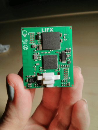
LIFX Wireless LED PCB

Back in 2012, the LIFX light bulb launched on Kickstarter, and was quite successful. This wireless LED lightbulb uses a combination of WiFi and 6LoWPAN to create a network of lightbulbs within your house. Context Information Security took a look into these devices, and found some security issues.

The LIFX system has a master bulb. This is the only bulb which connects to WiFi, and it sends all commands out to the remaining bulbs over 6LoWPAN. To keep the network up, any bulb can become a master if required. This means the WiFi credentials need to be shared between all the bulbs.

Looking into the protocol, an encrypted binary blob containing WiFi credentials was found. This binary could easily be recovered using an AVR Raven evaluation kit, but was not readable since it was encrypted.

After cracking a bulb apart, they found JTAG headers on the main board. A BusBlaster and OpenOCD were used to communicate with the chip. This allowed the firmware to be dumped.

Using IDA Pro, they determined that AES was being used to encrypt the WiFi credentials. With a bit more work, the key and initialization vector was extracted. With this information, WiFi credentials sent over the air could be decrypted.

The good news is that LIFX fixed this issue. Now they generate an encryption key based on WiFi credentials, preventing a globally unique key from being used.

[via reddit]

Overwriting A Protected AVR Bootloader

Logo for the FIgnition 8 bit computer project

A bootloader is typically used to update application code on a microcontroller. It receives the new program from a host, writes it to flash, verifies the program is valid, and resets the microcontroller. Perhaps the most ubiquitous example is the Arduino bootloader which allows you to load code without an AVR programmer.

The bootloader resides in a special part of memory, which is protected. On the AVR, it isn’t possible to write to the bootloader memory from the application code. This is to prevent you from accidentally breaking the bootloader and bricking the device.

However, it can be useful to write to the bootloader memory. The best example would be when you need to update the bootloader itself. To accomplish this, [Julz] found a workaround that defeats the AVR bootloader protection.

The challenge was to find a way to execute the Store Program Memory (spm) instruction, which can only be executed by the bootloader. [Julz] managed to make use of the spm instruction in the existing bootloader by counting cycles and modifying registers at the right time.

Using this technique, which [Julz] calls BootJacker, the Fignition 8 bit computer could have its bootloader updated. However, this technique would likely allow you to modify most bootloaders on AVR devices.

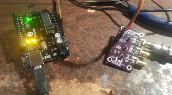
A SI5351 clock generator chip and an Arduino

Generate Clocks With The SI5351 And An Arduino

If you’re dealing with RF, you’ll probably have the need to generate a variety of clock signals. Fortunately, [Jason] has applied his knowledge to build a SI5351 library for the Arduino and a breakout board for the chip.

The SI5351 is a programmable clock generator. It can output up to eight unique frequencies at 8 kHz to 133 MHz. This makes it a handy tool for building up RF projects. [Jason]’s breakout board provides 3 isolated clock outputs on SMA connectors. A header connects to an Arduino, which provides power and control over I2C.

If you’re looking for an application, [Jason]’s prototype single-sideband radio shows the chip in action. This radio uses two of the SI5351 clocks: one for the VFO and one for the BFO. This reduces the part count, and could make this design quite cheap.

The Arduino library is available on Github, and you can order a SI5351 breakout board from OSHPark.

Electric Chainsaw Teardown

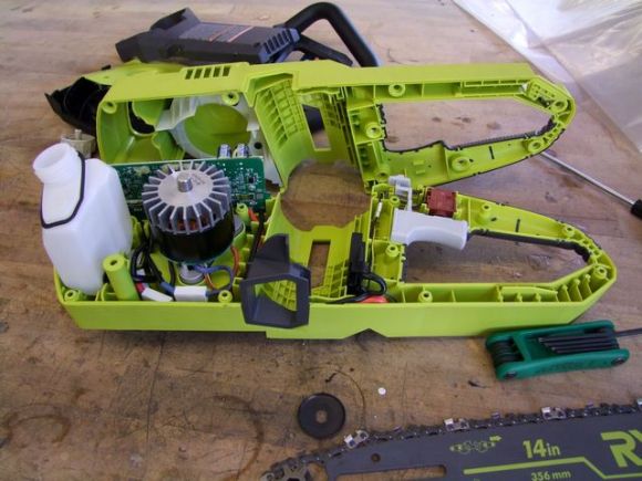
An electric chainsaw with its case removed

For his Beyond Unboxing series, [Charles] tore apart a Ryobi cordless chainsaw to get a better look at how this battery powered tool works.

Inside he found a three-phase motor and controller. This motor looks like it could be useful in other projects since it has a standard shaft. The battery pack was popped open to reveal a set of LG Chem 21865 cells, and some management hardware.

With all the parts liberated from the original enclosure, [Charles] set up the motor, controller, and battery on the bench. With a scope connected, some characterization of the motor could be done. A load was applied by grabbing the spinning shaft with welding gloves. [Charles] admits that this isn’t the safest way to test a motor.

While it is a very fast motor, the cut-in speed was found to be rather low. That means it can’t start a vehicle from a stop, but could be useful on e-bikes or scooters which are push started.

This chainsaw a $200 motor, controller, and battery set that could be the basis of a DIY scooter. It sounds great too, as the video after the break demonstrates.

[Thanks to Dane for the tip!]

Continue reading “Electric Chainsaw Teardown”

Autonomous Balloon Popping

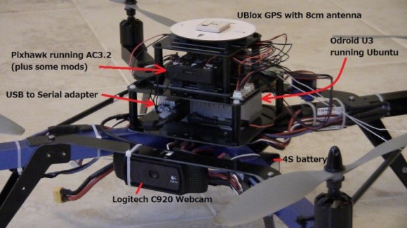
Quadcopter drone for popping balloons

Taking on an autonomous vehicle challenge, [Randy] put together this drone which can locate and pop balloons. It’s been assembled for this year’s Sparkfun Autonomous Vehicle Competition, which will challenge entrants to locate and pop 99 luftbaloons red balloons without human intervention.

The main controller for this robot is the Pixhawk, which runs a modified version of the ArduCopter firmware. These modifications enable the Pixhawk to receive commands from an Odroid U3 computer module. The Odroid uses a webcam to take images, and then processes them using OpenCV. It tries to locate large red objects and fly towards them.

The vision processing and control code on the Odroid was developed using MAVProxy and Drone API. This allows for all the custom code to be developed using Python.

The Sparkfun AVC takes place tomorrow — June 21st in Boulder, Colorado. You can still register to spectate for free. We’re hoping [Randy]’s drone is up to the task, and based on the video after the break, it should be able to complete this challenge.

Continue reading “Autonomous Balloon Popping”

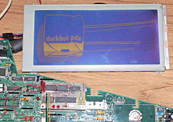
Dorkbot logo on a large LCD display

Reverse Engineering LCD Displays

Over at DorkbotPDX in Portland, a member showed up with a stack of large LCD displays from point of sale terminals. [Paul] took it upon himself to reverse engineer the displays so that they can be recycled in future projects.

The control circuit for this LCD resides on a rather large PCB with quite a variety of components. The board was reduced to three main components: an MSM6255 display controller, a 32k RAM chip which is used as the framebuffer, and a tri-state driver.

With all the unneeded components out of the way, a custom board based around an ATmega88 MCU was added. This board was soldered in to interface with the LCD controller’s bus. This allows data to be written from the 128k flash ROM on the custom board into the frame buffer. Once this is done, the display controller will display the data on the LCD.

Now that data could be written, [Paul] figured out the correct configuration for the display controller. That was the final piece in getting images to show up correctly on the display. If you happen to find some old Micros 2700 POS terminals, [Paul]’s detailed write-up will help you scavenge the displays.