Retrotechtacular: How Communism Made Televisions

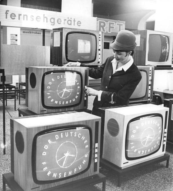
For those of us who lived through the Cold War, there’s still an air of mystery as to what it was like on the Communist side. As Uncle Sam’s F-111s cruised slowly in to land above our heads in our sleepy Oxfordshire village it was at the same time very real and immediate, yet also distant. Other than being told how fortunate we were to be capitalists while those on the communist side lived lives of mindless drudgery under their authoritarian boot heel, we knew nothing of the people on the other side of the Wall, and God knows what they were told about us. It’s thus interesting on more than one level to find a promotional film from the mid 1970s showcasing VEB Fernsehgerätewerk Stassfurt (German, Anglophones will need to enable subtitle translation), the factory which produced televisions for East Germans. It provides a pretty comprehensive look at how a 1970s TV set was made, gives us a gateway into the East German consumer electronics business as a whole, and a chance to see how the East Germany preferred to see itself.

Black and white photograph of a display of televisions displaying a DDR Deutsche Frensehfunk logo, with an attendant adjusting one of the sets.
The RFT range of televisions in the Städtisches Kaufhaus exhibition center for the 1968 Leipzig Spring Fair. Bundesarchiv, CC-BY-SA 3.0

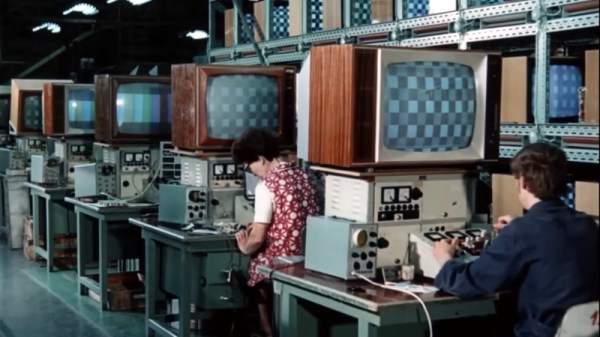
The sets in question are not too dissimilar to those you would have found from comparable west European manufacturers in the same period, though maybe a few things such as the use of a tube output stage and the lack of integrated circuits hints at their being a few years behind the latest from the likes of Philips or ITT by 1975. The circuit boards are assembled onto a metal chassis which would have probably been “live” as the set would have derived its power supply by rectifying the mains directly, and we follow the production chain as they are thoroughly checked, aligned, and tested. This plant produces both colour and back-and-white receivers, and since most of what we see appears to be from the black-and-white production we’re guessing that here’s the main difference between East and West’s TV consumers in the mid ’70s.

The film is at pains to talk about the factory as a part of the idealised community of a socialist state, and we’re given a tour of the workers’ facilities to a backdrop of some choice pieces of music. References to the collective and some of the Communist apparatus abound, and finally we’re shown the factory’s Order of Karl Marx. As far as it goes then we Westerners finally get to see the lives of each genosse, but only through an authorised lens. Continue reading “Retrotechtacular: How Communism Made Televisions”

Hackaday Prize 2023: This Differential Scope Probe Is Smarter Than It Looks

A differential probe, a device for measuring the voltage between two points in a circuit rather than the voltage between a point and ground, it an extremely useful addition to any electronics bench. Inside such a probe you’ll usually find a fancy op-amp working as a differential amplifier, and for correct operation they require careful adjustment to null out DC bias and achieve the maximum common mode rejection. We particularly like [Craig D]’s probe, because these adjustments are taken care of automatically by a microcontroller.

The analogue path provides a lesson for anyone interested in instrumentation signal path design, with the signal conditioning and compensation circuits feeding an AD8130 differential amplifier. Another amplifier samples the output voltage and feeds it to the ADC in the microcontroller. Common mode adjustment is taken care of by a digital potentiometer chip, and DC offset by the microcontroller’s DAC. Controlling all this is an ATSAMD10 chip, and the power is derived from the scope’s USB interface.

All in all it’s an extremely well-executed device, and one we’d be happy to have on our bench at any time. It’s by no means the first differential probe we’ve brought you, here’s another.


Proper Video, From An ESP32

Back in the day a miniature television, probably on a wristwatch, was the stuff of science fiction. Now, it’s something which can be done with a commodity microcontroller, as [Atomic14] shows us with the ESP32-TV that plays both video and sound. Even with modern silicon it’s still somewhat pushing the envelope.

As he explains in the video below the break, not all formats are simple enough to be decoded on the fly by a microcontroller. But he finds an AVI file to be within its capabilities which can be created with a bit of ffmpeg wizardry. The board is a fairly standard ESP32 device with an I2C bus, and the video stream isn’t too fast for this meager interface. You’ll maybe recognize the Muppets clip, but it’s possible that the early-80s BBC comedy staple The Young Ones might have passed you by if you’re not British.

We think this code is likely to be of use in quite a few projects, and it would be great to see it further refined. Small video players for not a lot of money can never be a bad thing.

Previous ESP32 video projects which have appeared on these pages have been more likely to involve driving a display directly.

Continue reading “Proper Video, From An ESP32”

Hackaday Prize 2023: An Anti-Tremor Handle, With No Electronics

Many of us will have seen the various active assistive devices which have appeared over the last few years to help people with a hand tremor. Probably the best known was a fork with a set of servos and an accelerometer, that kept the end of the utensil steady despite the owner’s hand movements. It’s a field which has the potential to help many people, but it’s undeniable that such technology comes with a cost.

What if the same effect could be achieved passively, without all those electronics? It’s something [Jacob] is investigating with his mechanical anti-tremor cup handle. It’s a university project completed as part of his studies so it’s very much a work-in-progress which if we’re being fair isn’t quite there yet, but we think the potential in this idea of bringing a useful assistive device at least bears further attention.

The write-up is available as a Norwegian PDF file so takes a little bit of Google Translate cut and pasting for an Anglophone. Sadly due to what must be report format requirements set by the university it’s long on procedure and shorter on engineering calculations than we’d like, but there’s an attempt to calculate the properties of the helical springs in each of the joints to match the likely forces. Our intuition is that the design as shown would require significantly more mass on the end of it than that of the mug and beverage alone to achieve some form of stability, but despite that as we said it’s an interesting enough idea that it deserves more thought.

Hand tremor assistive devices have appeared more than once on these pages before, here’s one for soldering that enlists the aid of a camera gimbal.

Will Nickel-Hydrogen Cells Be The Energy Storage Holy Grail?

You may have heard us here remarking in the past, that if we had a pound, dollar, or Euro for every miracle battery technology story we heard that was going to change the world, we would surely be very wealthy by now. It’s certainly been the case that many such pronouncements refer to promising chemistries that turn out only to be realizable in a lab, but here there’s news of one with a bit of pedigree. Nickel hydrogen batteries have a long history of use in space, and there’s a startup producing them now for use on the ground. Could they deliver the energy storage Holy Grail?

The cathode in a nickel-hydrogen battery is formed by nickel hydroxide, and the anode is formed of hydrogen. If a gas as an anode sounds far fetched, we’re guessing that their structure is similar to the zinc-air battery, in which zinc hydroxide forms in a paste of powdered zinc, and works against oxygen from the air over a porous conductive support. What gives them their exciting potential is their ability to take more than 30,000 charge/discharge cycles, and their relative safety when compared to lithium ion cells. Hydrogen in a pressure vessel might not seem the safest of things to have around, but the chemistry is such that as the pressure increases it reacts to form water. The cost of the whole thing is reduced further as new catalysts have replaced the platinum used by NASA on spacecraft.

We really hope that these batteries will be a success, but as always we’ll wait and see before calling it. They may well be competing by then with the next generation of zinc-air cells.

Feed Your Fasteners In Line, With A Bowl Feeder

If you spend much time around industrial processes, you may have seen a vibrating bowl feeder at work. It’s a clever but simple machine that takes an unruly pile of screws or nuts and bolts, and delivers them in a line the correct way up. They do this by shaking the pile of fasteners in a specific way — a spiral motion which encourages them to work to the edge of the pile and align themselves on a spiral track which leads to a dispenser. It’s a machine [Fraens] has made from 3D printed parts, and as he explains in the video below the break, there’s more to this than meets the eye.

The basic form of the machine has a weighted base and an upper bowl on three angled springs. Between the two is an electromagnet, which provides the force for the vibration. The electromagnet needed to be driven with a sine wave which he makes with an Arduino and delivers as PWM via an H-bridge, but the meat of this project comes in balancing the force and frequency with the stiffness of the springs. He shows us the enormous pile of test prints made before the final result was achieved, and it’s a testament to the amount of work put into this project. The final sequence of a variety of objects making the march round the spiral is pure theatre, but we can see his evident satisfaction in a job well done.

Oddly this isn’t the first bowl feeder we’ve seen, though it may be one of the most accomplished. We particularly like this tiny example for SMD parts.

Continue reading “Feed Your Fasteners In Line, With A Bowl Feeder”

How To Chase The Beam With A Z80

The more accomplished 8-bit microcomputers of the late 1970s and early 1980s had a dedicated display chip, a CRT controller. This took care of all the jobs associated with driving a CRT display, generating the required timing and sequencing all the dots to make a raster. With a CRT controller on hand the CPU had plenty of time to do other work, but on some cheaper machines there was no CRT controller and the processor had to do all the work of assembling the display itself.

[Dr. Matt Regan] had a Sinclair ZX81 which relied on this technique, and he’s put up the first of what will become a series of videos offering a deep dive into this method of creating video. The key to its operation lies in very careful use of timing, with operations executed to keep a consistent number of clock cycles per dot on the display. He’s making a very low resolution version of the display in the first video, which he manages to do with only an EPROM and a couple of 74 logic chips alongside the Z80. We’re particularly impressed with the means of creating the sync pulses, using opcodes carefully chosen to do nothing of substance except setting a particular bit.

This method of assembling a display on such a relatively slow microprocessor has the drawback of no means of creating a grayscale, and of course it’s only available in glorious black and white. But it’s the system which gave a first experience of computing to millions, and for that we find the video fascinating. Take a look, below the break.

If this has caused you to yearn for all things Sinclair, read our tribute to the man himself.

Continue reading “How To Chase The Beam With A Z80”