A trope in open source commentary over the last decades has been the phrase “Is this the year of Linux on the desktop?”, as though the open source OS will finally break through and challenge Windows. In fact the process has been one of stealth rather than explosive growth, as the likes of ChromeOS with its Linux underpinnings become the go-to choice for an inexpensive consumer laptop. In the phone arena the same has happened with Android, as most users have no idea that a Linux foundation lies beneath their Samsung Galaxy or Google Pixel.
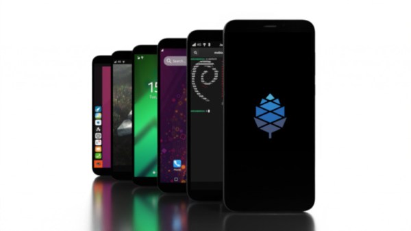
Fully open-source via Android on the phone has been very slow to arrive, but could that be changed by the arrival of Pine64’s PinePhone Pro? The new device will be available alongside their existing PinePhone, and will continue the dream of a fully open-source mobile phone with its increased-specification hardware.
As much as the specs of one black slab versus another matter, at its heart is a 1.5 GHz Rockchip RK3399S hexa-core SoC alongside 4 GB of dual-channel LPDDR4 RAM. This compares well to the original PinePhone’s quad-Core Allwinner A64 at 1.152 GHz and 3 GB LPDDR3 RAM, so it’s clear that there is plenty of capability in this phone.
Any phone whether open-source or not will however live or die on the quality of its software and support, so for this model to be a real success outside the realm of extreme open-source devotees we think that Pine64 will need to be prepared to up their game when it comes to what happens after hardware delivery. It’s fair to say that some of their previous products have been a little lacklustre in this department, with hardware bugs remaining unfixed. Their approach of relying on the community of users to deliver software support has not so far returned a stable experience for users of the original PinePhone. We understand that their intention is to provide a developer’s phone, but developers need to place phonecalls and take pictures too.
We’ve seen some PinePhone owners commenting to this effect, and though we’re fans of Pine64 and like what they are trying to do, we have to admit that those users have a point. If they were prepared to put some effort into software development to the extent of providing an official OS image with let’s say Plasma Mobile, a working phone app, a working web browser, and responsive phone features such as instant on and off, even at the expense of charging more for the phone itself, we think that they’ll be on to a winner. Otherwise they’ll remain as the really cool open-source phone that only your kernel-wizard friends own, and even then they use a Google Pixel as their everyday phone. Please Pine64, prove us wrong!
Last month our colleague Brian Cockfield took us on a tour of his PinePhone.