Trials And Tribulations In Sending Data With Wires

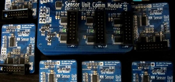
When working on a project that needs to send data from place to place the distances involved often dictate the method of sending. Are the two chunks of the system on one PCB? A “vanilla” communication protocol like i2c or SPI is probably fine unless there are more exotic requirements. Are the two components mechanically separated? Do they move around? Do they need to be far apart? Reconfigurable? A trendy answer might be to add Bluetooth Low Energy or WiFi to everything but that obviously comes with a set of costs and drawbacks. What about just using really long wires? [Pat] needed to connect six boards to a central node over distances of several feet and learned a few tricks in the process.

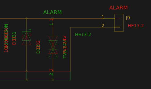
When connecting two nodes together via wires it seems like choosing a protocol and plugging everything in is all that’s required, right? [Pat]’s first set of learnings is about the problems that happen when you try that. It turns out that “long wire” is another way to spell “antenna”, and if you happen to be unlucky enough to catch a passing wave that particular property can fry pins on your micro.

Plus it turns out wires have resistance proportional to their length (who would have though!) so those sharp square clock signals turn into gently rolling hills. Even getting to the point where those rolling hills travel between the two devices requires driving drive the lines harder than the average micro can manage. The solution? A differential pair. Check out the post to learn about one way to do that.

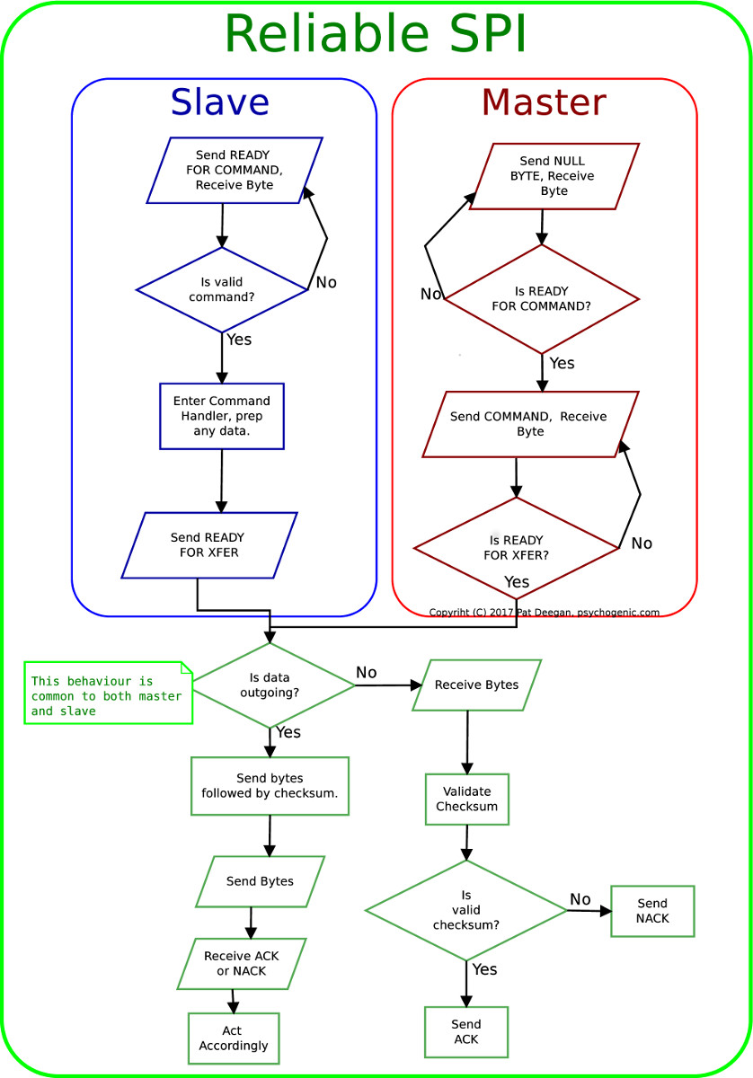
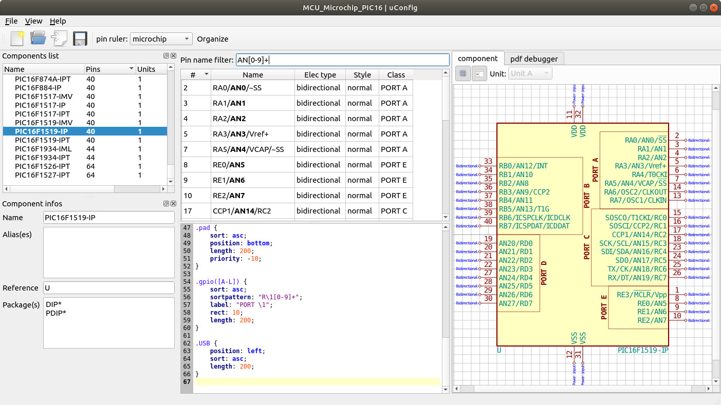
It looks like [Pat] needed to add USB to this witches brew and ended up choosing a pretty strange part from FTDI, the Vinculum II. The VNC2 seemed like a great choice with a rich set of peripherals and two configurable USB Host/Peripheral controllers but it turned out to be a nightmare for development. [Pat]’s writeup of the related troubles is a fun and familiar read. The workaround for an incredible set of undocumented bad behaviors in the SPI peripheral was to add a thick layer of reliability related messaging on top of the physical communication layer. Check out the state machine for a taste, and the original post for a detailed description.

Advanced Techniques For Using Git With KiCAD

For most developers “distributed version control” probably means git. But by itself git doesn’t work very well with binary files such as images, zip files and the like because git doesn’t know how to make sense of the structure of an arbitrary blobs of bytes. So when trying to figure out how to track changes in design files created by most EDA tools git doesn’t get the nod and designers can be trapped in SVN hell. It turns out though KiCAD’s design files may not have obvious extensions like .txt, they are fundamentally text files (you might know that if you’ve ever tried to work around some of KiCAD’s limitations). And with a few tweaks from [jean-noël]’s guide you’ll be diffing and merging your .pro’s and .sch’s with aplomb.

There are a couple sections to the document (which is really meant as an on boarding to another tool, which we’ve gotten to in another post). The first chunk describes which files should be tracked by the repo and which the .gitignore can be configured to avoid. If that didn’t make any sense it’s worth the time learning how to keep a clean repo with the magic .gitignore file, which git will look for to see if there are any file types or paths it should avoid staging.

The second section describes how you can use two nifty git features, cleaning and smudging, to dynamically modify files as they are checked in and out of the repo. [jean-noël]’s observation is that certain files get touched by KiCAD even if there are no user facing changes, which can clutter patch sets with irrelevant changes. His suggested filters prevent this by stripping those changes out as files get checked in. Pretty slick.

Visual Schematic Diffs In KiCAD Help Find Changes

When writing software a key part of the development workflow is looking at changes between files. With version control systems this process can get pretty advanced, letting you see changes between arbitrary files and slices in time. Tooling exists to do this visually in the world of EDA tools but it hasn’t really trickled all the way down to the free hobbyist level yet. But thanks to open and well understood file formats [jean-noël] has written plotgitsch to do it for KiCAD.

In the high(er)-end world of EDA tools like OrCAD and Altium there is a tight integration between the version control system and the design tools, with the VCS is sold as a product to improve the design workflow. But KiCAD doesn’t try to force a version control system on the user so it doesn’t really make sense to bake VCS related tools in directly. You can manage changes in KiCAD projects with git but as [jean-noël] notes reading Git’s textual description of changed X/Y coordinates and paths to library files is much more useful for a computer than for a human. It basically sucks to use. What you really need is a diff tool that can show the user what changed between two versions instead of describe it. And that’s what plotgitsch provides.

plotgitsch’s core function is to generate images of a KiCAD project at arbitrary Git revisions. After that there are two ways to view the output. One is to generate images of each version which can be fed into a generic visual diff tool (UNIX philosophy anyone?). The documentation has an example script to help facilitate setting this up. The other way generates a color coded image in plotgitsch itself and opens it in the user’s viewer of choice. It may not be integrated into the EDA but we’ll take one click visual diffs any day!

Automagic Tool Makes KiCAD Schematic Symbols From PDFs

Last time we talked about a KiCAD tool it was to describe a way to make the zen-like task of manual assembly more convenient. But what about that most onerous of EE CAD tasks, part creation? Home makers probably don’t have access to expensive part library subscriptions or teams of people to create parts for them, so they are left to the tedium of creating them by hand. What if the dream tool existed that could read the darn PDF by itself and make a part? It turns out [Sébastien] made that tool and it’s called uConfig.

uConfig has a pretty simple premise. It scrapes manufacturer datasheets in PDF form, finds what it thinks are diagrams of parts with pin names, functions, etc, and emits the result as parts in a KiCAD library. To aid in the final conversion [Sébastien] added rules engine which consume his custom KiCAD Style Sheets which specify how to categorize pins. In the simple case the engine can string match or use regex to let you specify things like “all pins named VDD[A-C] should be power pins”. But it can also be used to move everything it thinks belongs to “GPIOB” and stick them on the bottom of the created symbol. We could imagine features like that would be of particular use breaking out gigantic parts like a 400 ball BeagleBone on a chip.

Thanks for the tip [arturo182]!

Interactive KiCAD BOMs Make Hand Assembly A Breeze

We’ve all been there; you finally get the last DigiKey box and now your desk is covered in parts to stuff into a shiny new PCB you’ve been working on. First stop? Passive town, population endless waves of 1uF capacitors. The first one goes in the upper left, then a little below that, then… once you get to C157 it’s getting pretty hard to remember exactly which parts go where. Enter the literally named InteractiveHtmlBom (IHB) to smooth this process out.

IHB makes the frustrating task of mapping lines in a BOM to a physical position on a board easy. The classic method is of course, to look at the BOM, then search the board for that designator and place the component. (You left the designators in the silk, right?) Or to look at the BOM, ask your CAD package to search for that part in the layout, then place. IHB generates a document that does this automagically.

A sample file from a familiar project

Run the tool, either standalone or as a plugin for KiCAD 5.0, and you get a folder with the new interactive BOM in it. There are a few view options but generally it presents a view of the BOM with designators and value in one pane and a wonderful render of the top and/or bottom of the board in another pane. When you hover over a BOM line it highlights the relevant parts in the board view! There are toggles for filtering by top and bottom of board, marking which parts have been placed, light and dark mode, etc. Plus the ability to filter and sort by designator and value. We would have been impressed if it was just a generator/viewer for those slick scrollable/pannable board renders!

Check out a very long GIF demo after the break, or explore one of many pre-created demo BOMs here. We’re partial to the OSPx201.

Thanks [GregDavill] for the tip!

Continue reading “Interactive KiCAD BOMs Make Hand Assembly A Breeze”

When Are Dumb LEDs The Smart Choice?

A couple years ago I got into making electronic conferences badges by building a device for DEFCON 25 shaped like a dragonfly. Like all badges the most important design factor was quite literally how flashy it was, and two years ago I delivered on that with ten RGB LEDs. At the time I planned to hand-assemble each and every of the 105 badges at my kitchen table. Given those constraints, and a desire for electrical and programmatic simplicity, I landed on using APA102s (DotStar’s in Adafruit parlance) in the common 5050 sized package. They were easy to place, easy to design with electrically, simple to control, and friendly to a human pick-n-place machine. Though by the end of the production run I had discovered a few problems, the APA102s were a success.

This year I made a new and improved version of the dragonfly, but applying my lessons learned led me to choose a very different LED architecture than 2017. I swapped out the smart LEDs for dumb ones.

Continue reading “When Are Dumb LEDs The Smart Choice?”

A CNC Woodworking Tool That Does The Hard Parts

Drawn along in the wake of the 3d printing/home shop revolution has been the accessibility of traditional subtractive CNC equipment, especially routers and mills. Speaking of, want a desktop mill? Try a Bantam Tools (née Othermachine) Desktop Milling Machine or a Carvey or a Carbide 3D Nomad. Tiny but many-axis general purpose mill? Maybe a Pocket NC. Router for the shop? Perhaps a Shapeoko, or an X-Carve, or a ShopBot, or a… you get the picture. [Rundong]’s MatchSticks device is a CNC tool for the shop and it might be classified as a milling machine, but it doesn’t quite work the way a more traditional machine tool does. It computer controls the woodworker too.

Sample joints the MatchSticks can cut

At a glance MatchSticks probably looks most similar to a Pocket NC with a big Makita router sticking out the side. There’s an obvious X-axis spoilboard with holes for fixturing material, mounted to a gantry for Z-axis travel. Below the big friendly handle on top is the router attached to its own Y-axis carriage. The only oddity might be the tablet bolted to the other side. And come to think of it the surprisingly small size for such an overbuilt machine. What would it be useful for? MatchSticks doesn’t work by processing an entire piece of stock at once (that what you’re for, adaptable human woodworker) it’s really a tool for doing the complex part of the job – joinery – and explaining to the human how to do the rest.

The full MatchSticks creation flow goes like this:

  1. Choose a design to make on the included interface and specify the parameters you want (size, etc).
  2. The MatchSticks tool will suggest what material stocks you need, and then ask you to cut them to size and prepare them using other tools.
  3. For any parts which require CNC work the tool will help guide the user to fixture the stock to its bed, then do the cutting itself.
  4. Once everything is ready for final assembly the MatchSticks will once again provide friendly instructions for where to pound the mallet.

In this way [rundong], [sarah], [jeremy], [ethan], and [eric] were able to build a much smaller machine tool without sacrificing much practical functionality. It’s almost software-like in it’s focus on a singular purpose. Why reinvent what the table saw can do when the user probably already has access to a table saw that will cut stock better? MatchSticks is an entire machine bent around one goal, making the hard stuff easier.

It’s worth noting that MatchSticks was designed as an exploration into computer/human interaction for the ACM Conference on Human Factors in Computing Systems so it’s not a commercial product quite yet (we’re eagerly waiting!). For a much more in depth look at the project and its goals and learnings the full research paper is available here. Their intro video is down after the break.

Thanks [ethan] for the tip!

Continue reading “A CNC Woodworking Tool That Does The Hard Parts”