WiFive55: More Than A Smart 555 Replacement

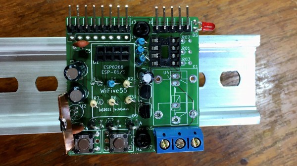
“You could’ve done that with a 555 timer.” But what if all you have on hand is an ESP8266? [TechColab] needed to control a solenoid valve with a short pulse via a solid-state relay (SSR) but found that the trusty 555 timer was tricky to set properly. Additionally, they wanted to add features, such as fixed pulse length, that were difficult to implement—even with multiple timers. Still wanting to keep things cheap and accessible, [TechColab] has created the WiFive55, a 555 replacement based on the ESP-01 ESP8266 board.

[TechColab] began by investigating existing ESP-01 solid-state relay boards but found that many of them momentarily enable the output on startup—a risk [TechColab] deemed unacceptable. This was resolved in the WiFive55 by adding an RC filter to the SSR output, eliminating the output glitches at the cost of slowing switching time to around 20 ms—an acceptable trade for many SSR applications.

Since they were going to design a new PCB to support this improved ESP-01 SSR controller, [TechColab] decided to go all-out. To support loads of widely varying sizes, the PCB supports an optoisolator that switches up to 1 A, a MOSFET that switches up to 2 A, and an on-board relay or SSR that can switch up to 3 A. For heavy loads, it includes connections for an off-board SSR, which allow it to switch whatever current the SSR can handle (easily over 50 A). Because the ESP-01 is slightly more capable than the 555, the WiFive55 supports control via WiFi, GPIO, serial, and push-button. Keeping with the WiFive55’s original role as a 555 replacement, it even includes a header exposing a 555-like trigger and output interface!

We always like seeing inexpensive boards like the ESP-01 being used to their full potential, and we can’t wait to see what software [TechColab] cooks up for this! If you’re interested in getting started with the ESP-01, you might consider starting with this guide to blinking an LED over WiFi.

Fan-tastic Misuse Of Raspberry Pi GPIO

[River] is a big fan of home automation. After moving into a new house, he wanted to assimilate two wirelessly controlled fan lights into his home automation system. The problem was this: although the fans were wireless, their frequency and protocol were incompatible with the home automation system.

Step one was to determine the frequency the fan’s remote used. Although public FCC records will reveal the frequency of operation, [River] thought it would be faster to use an inexpensive USB RTL-SDR with the Spektrum program to sweep the range of likely frequencies, and quickly found the fans speak 304.2 MHz.

Next was to reverse-engineer the protocol. Universal Radio Hacker is a tool designed to make deciphering unknown wireless protocols relatively painless using an RTL-SDR. [River] digitized a button press with it and immediately recognized it as simple on-off keying (OOK). With that knowledge, he digitized the radio commands from all seven buttons and was quickly able to reverse-engineer the entire protocol.

[River] wanted to use a Raspberry Pi to bring the fans into his home automation system, but the Raspberry Pi doesn’t have a 304.2 MHz radio. What it does have is user-programmable GPIO and the rpitx package, which converts a GPIO pin into a basic radio transmitter. Of course, the Pi’s GPIO pin’s aren’t long enough to efficiently transmit at 304.2 MHz, so [River] added a proper antenna, as well as a low-pass filter to clean up the transmitted signal. The rpitx package supports OOK out of the box, so [River] was quickly able get the Pi controlling his fan in no time!

If you’d like to do some more low-cost home automation, check out this approach to using a Raspberry Pi to control some bargain-bin smart plugs.

Music Production Studio In A Box

[Emil Smith] is an electronic music producer in the Greater London area. He spent a lot of time commuting in and out of central London, so he decided to put together COVERT-19, a portable music production studio. After making a couple of prototypes, [Emil] settled on what he needed from his portable studio: a sampler, a sequencer, a synthesizer, a mixer, and a way to record his work.

[Emil] didn’t overlook any details with his mechanical design. Taking the beautiful London weather into account, he designed a laser-cut plywood case that has a neoprene foam gasket to keep water out when closed and put all of the inputs and outputs on the interior of the case. Inside the case, he opted for machine screws with threaded inserts so he could disassemble and reassemble his creation as often as he liked, and he included gas springs to keep the studio open while he’s making music. [Emil] even thought to include ventilation slots to keep the built-in PC cool!

A portable studio is useless without a power supply, so [Emil] taught himself some circuit theory and bought his first soldering iron in order to create the custom power delivery system. Power is supplied by a battery of twelve 18650 cells with switching converters to supply the three different voltages his studio needs. Even with all of his music-making gear, he manages to get about four hours of battery life!

The music-making gear consists of a sequencer and synthesizer as well as a touch-screen NUC PC running Xubuntu. The built-in PC runs software that allows him to mix the audio, apply extra effects, record his creations, and save his patches when he’s done working. The system even has an extra MIDI output and audio input to allow it to incorporate an external synthesizer.

If you’re interested in getting started with MIDI synthesizers, but you’re more interested in building than buying, check out the KELPIE.

A Deep Dive Into E-Ink Tag Hacking

Over the last decade or so, e-ink price tags have become more and more ubiquitous, and they’ve now reached the point where surplus devices can be found inexpensively on various websites. [Dmitry Grinberg] found a few of these at bargain-basement prices and decided to reverse engineer and hack them into monochrome digital picture frames.

Often, the most difficult thing about repurposing surplus hardware is the potential lack of documentation. In the two tags [Dmitry] hacked, not only are the labels not documented at all, one even has an almost-undocumented SoC controlling it. After some poking around and some guesswork, he was able to find connections for both a UART and an SWD debugging interface. Fortunately, the manufacturers left the firmware unprotected, so dumping it was trivial.

Even with the firmware dumped, code for controlling peripherals (especially wireless devices) is often inscrutable. [Dmitry] overcomes this with a technique he calls “Librarification” in which he turns the manufacturer’s firmware into libraries for his custom code. Once he was able to implement his custom firmware, [Dmitry] developed his own code to wirelessly download and display both gray-scale and two-color images.

Even if you’re not interested in hacking e-ink tags, this is an incredible walk-through of how to approach reverse-engineering an embedded or IoT device. By hacking two different tags with completely different designs, [Dmitry] shows how to get into these systems with intuition, guesswork, and some sheer persistence.

If you’d like to see some more of [Dmitry]’s excellent reverse-engineering work, take a look at his reverse-engineering and ROM dump of the PokeWalker. If you’re interested in seeing what else e-ink tags can be made to do, take a look at this weather station made from the same 7.4″ e-ink tag.

A Hi-Fi Speaker From Some Foil And Magnets

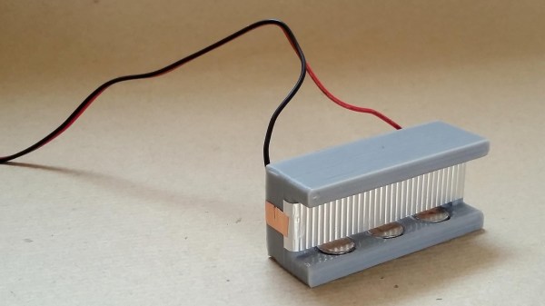
In the world of speakers, mass is the enemy of high frequency response. In order to get the crispest highs, some audiophiles swear by speakers in which the moving element is just a thin ribbon of metal foil. As the first step towards building a set of ribbon headphones, [JGJMatt] has designed a compact ribbon speaker made from aluminum foil.

A 3D-printed body holds six permanent magnets, which produce the static magnetic field necessary for the speaker to work. The sound itself is produced by a corrugated aluminum diaphragm made by taking a strip of foil and creasing it with a gear. Aluminum is difficult to solder, so electrical contact is made with a couple of short segments of copper tape. A little Blu Tack and glue hold it all together, and the result is stunning in its simplicity.

Check out the video after the break to hear how it sounds. If you want to try this yourself, it’s important to remember that ribbon speakers have very low input impedances (0.1 Ω for this design), so in order to prevent damage to your amplifier, a transformer or series resistor must be used to bring the impedance up to the 4-8 Ω your amplifier expects.

[JGJMatt] is no newcomer to exotic speaker technology—check out these thin distributed-mode loudspeakers they made! If you’re more interested in recording music than playing it, you might want to read about how a metal ribbon suspended in a magnetic field is used to make incredible microphones. Shout out to [Itay] for the tip. Continue reading “A Hi-Fi Speaker From Some Foil And Magnets”

Build-It-Yourself LC Meter

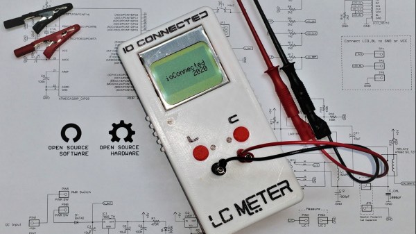
A basic digital multimeter (DMM) is usually the first measurement tool the aspiring electronics tinkerer buys. Even a bargain-bin DMM will happily measure voltage, current, and resistance; check continuity; and may even have a mode to measure transistor gain. Every toolbox needs at least one DMM, but most have an crucial limitation— they can’t measure two of the fundamental electrical quantities: inductance and capacitance. On Hackaday.io, [core weaver] has developed an open-source LC meter to allow you to build your own tool to measure inductance and capacitance.

[core weaver]’s design is all through-hole, so even just assembling one would be a great exercise for someone getting started in electronics. However, he didn’t just release a design, in a series of videos he goes through the theory of the device’s operation; explains the design of the circuit, firmware, and case; and shows you how to put it all together. For times when you need to measure a lot of parts (e.g. if you have to sort a bag of cheap capacitors looking for specific value), he’s even developed a desktop program to save you some trouble!

The finished meter looks incredible! If you want to build one for yourself, he’s put all of the files up on GitHub, and we highly recommend you check out his first video after the break. If you’d like to build yourself a 6.5-digit DMM to go with our LC Meter, consider this one which even has a home-built ADC.

Continue reading “Build-It-Yourself LC Meter”

Injecting Bugs With An Electric Flyswatter

Hardware fault injection uses electrical manipulation of a digital circuit to intentionally introduce errors, which can be used to cause processors to behave in unpredictable ways. This unintentional behavior can be used to test for reliability, or it can be used for more nefarious purposes such as accessing code and data that was intended to be inaccessible. There are a few ways to accomplish this, and electromagnetic fault injection uses a localized electromagnetic pulse to flip bits inside a processor. The pulse induces a voltage in the processor’s circuits, causing bits to flip and often leading to unintentional behavior. The hardware to do this is very specialized, but [Pedro Javier] managed to hack a $4 electric flyswatter into an electromagnetic fault injection tool. (Page may be dead, try the Internet Archive version.)

[Pedro] accomplishes this by turning an electric flyswatter into a spark-gap triggered EMP generator. He removes the business end of the flyswatter and replaces it with a hand-wound inductor in series with a small spark gap. Pressing the power button on the modified flyswatter charges up the output capacitor until the developed voltage is enough to ionize the air in the spark gap, at which point the capacitor discharges through the inductor. The size of the spark gap determines the charge that is built up—a larger gap results in a larger charge, which produces a larger pulse, which induces a larger voltage in the chip.

[Pedro] demonstrates how this can be used to produce arithmetic glitches and even induce an Arduino to dump its memory. Others have used electromagnetic fault injection to corrupt SRAM, and intentionally glitching the power supply pins can also be used to access otherwise protected data.