Breaking Down The USB Keyboard Interface With Old-Fashioned Pen And Paper

What is better for gaming, old PS/2 style keyboards, or modern USB devices? [Ben Eater] sets out to answer this question, but along the way he ends up breaking down the entire USB keyboard interface.

It turns out that PS/2 and USB are very, very different. A PS/2 keyboard sends your keystroke every time you press a key, as long as it has power. A USB keyboard is more polite, it won’t send your keystrokes to the PC until it asks for them.

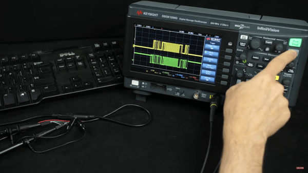
To help us make sense of USB’s more complicated transactions, [Ben] prints out the oscilloscope trace of a USB exchange between a PC and keyboard and deciphers it using just a pen and the USB specification. We were surprised to see that USB D+ and D- lines are not just a differential pair but also have more complicated signaling behavior. To investigate how USB handles multi-key rollover, [Ben] even borrowed a fancy oscilloscope that automatically decodes the USB data packets.

It turns out that newer isn’t always better—the cheap low-speed USB keyboard [Ben] tested is much slower than his trusty PS/2 model, and even a much nicer keyboard that uses the faster full-speed USB protocol is still only just about as fast as PS/2.

If you’d like to delve deeper into keyboard protocols, check out [Ben]’s guide to the PS/2 keyboard interface, complete with a breadboarded hardware decoder. If these keyboards have too many keys for your taste, you might consider this USB Morse code keyboard. Thanks to Peter Martin for the Tip!

Air Extractor Automatically Gives AC A Boost

Portable air conditioning units are a great way to cool off a space during the hot summer months, but they require some place to blow the heat they’ve removed from your room. [VincentMakes] got a portable AC unit for his home, but he found that the place he wanted to put it was too far from the only window he could use to dump the hot air. Having too long of a duct on the hot air exhaust increases the back pressure on the fan which could cause it to prematurely fail, so [Vincent] used an extractor fan to automatically give is AC unit’s exhaust a boost on its way to the window.

Because his AC can operate at low, medium, and high speeds, he chose an extractor fan that also supported multiple speeds and took care to match the airflow of the AC and extractor fan to avoid putting too much strain on either fan. He designed a system to automatically set the speed of the boosting fan to match that of the AC using a Hall effect current sensor to measure the AC unit’s power draw and an Arduino Nano for control. A custom PCB interfaces the Nano to the Hall Sensor and control relays, and we have to applaud [Vincent] for keeping the +5V DC and 230V AC far, far away from each other. In addition to this fine electronics work, [Vincent] also built an enclosure for the fan controller that allows the fan to be mounted on top at an angle, which helps avoid having hard bends in the exhaust duct.

If this has you thinking about smart air conditioners to keep cool this summer, check out this ESP8266-powered smart AC system, or this Raspberry Pi-based system that controls both AC and blinds!

Python Runs Through A Zombified 8-Bit AVR

As amazing as CircuitPython is, it hasn’t yet been ported to any 8-bit microcontrollers. [Chris Heo] was unsatisfied with his inability to use Python on his 8-bit ATmega4808 AVR, so he worked out a way to zombify it and bend it to his will using Python on his PC.

The trick to making this all work is the UPDI interface: a single-wire UART interface for programming and debugging Microchip’s newer 8-bit AVR microcontrollers. UPDI reaches deep into the microcontroller’s core, allowing you to stop and start execution of microcontroller code and access all of the onboard data and I/O. [Chris] realized this could be used to stop execution of any code running on the AVR and directly control the output pins using the pyupdi library. Since UPDI lets him modify the AVR’s I/O registers, he was also able to blink an LED and use the microcontrollers UART to send a message back to his PC without compiling a single line of code.

This may seem like an entirely unnecessary hack, but for devices too small or basic to have a JTAG interface for debugging this could be the best way to test and debug peripherals in an assembled circuit. We hope this catches on and would love to see how much of the chip can be controlled in this way. Maybe this will make it easy to experiment with the programmable logic that’s on some of the newer AVRs.

Using CanoPy To Visualize The CAN Bus

As cars have become more sophisticated electronically, understanding the CAN bus that forms the backbone of automotive digital systems has become more and more important for hacking cars. Inexpensive microcontroller CAN interfaces have made obtaining the raw CAN bus traffic trivial, but interpreting that traffic can be pretty challenging. In order to more easily visualize CAN traffic, [TJ Bruno] has developed CanoPy, a Python tool for visualizing CAN messages in real time.

A basic PC CAN interface simply dumps the bus’s message traffic into the terminal, while more sophisticated tools organize messages by the address of their intended recipients. Both of these approaches digitally lift the hood and let you examine what your car is thinking, but the wall-of-numbers approach makes finding the patterns that hold the keys to reverse engineering difficult. Automatically plotting the data with CanoPy makes finding correlations much easier, after which the text-based tools can be used to focus in on a few specific addresses.

Continue reading “Using CanoPy To Visualize The CAN Bus”

Using Docker To Sail Through Open-Source Xilinx FPGA Development

Until a few years ago, developing for FPGAs required the use of proprietary locked-down tools, but in the last few years, the closed-source dam has burst, and open-source FPGA tools such as Yosys, SimbiFlow, and Icestorm have come flooding out. Setting up a build environment for these exciting new tools can still be quite a challenge, but [Carlos Eduardo] has decided to make setting up an open-source toolchain for Xilinx FPGAs a breeze with Docker.

His image only has three prerequisites: Docker, Python 3, and OpenOCD (which is used to load your FPGA with your bespoke bitfile). After the Docker image has been built and all of the tools installed, [Carlos] guides you through using Python, FuseSoc, and SymbiFlow to build your first open-source Xilinx FPGA project.

In addition to making setup a whole lot easier, utilizing containers allows the same development environment to be built on Linux, Mac, and Windows (using WSL), which will make life a lot easier for teams working across different OSs.  [Carlos’s] Dockerfile is unique because it supports the popular Artix-7 series of FPGAs — for the Lattice FPGAs that have been supported for a lot longer, there are existing Docker files already up on DockerHub. It’s easier than installing the vendor’s toolchain!

If this has you thinking it might be time to dip your toes into open-source FPGA development, check out this rundown of open-source FPGA tools from the 2019 Superconference.

Taking Reverse Engineering To The Skies: Cheap Drone Gets PX4 Autopilot

Sometimes bad software is all that is holding good hardware back. [Michael Melchior] wanted to scavenge some motors and propellers for another project, so he bought an inexpensive quadcopter intending to use it for parts. [Michael] was so surprised at the quality of the hardware contained in his $100 drone that he decided to reverse engineer his quadcopter and give the autopilot firmware a serious upgrade.

Upon stripping the drone down, [Michael] found that it came with a flight management unit based on the STM32F405RG, an Inertial Measurement Unit, magnetic compass, barometric pressure sensor, GPS, WiFi radio, camera with tilt, optical flow sensor, and ultrasonic distance sensor, plus batteries and charger! The flight management unit also had unpopulated headers for SWD, and—although the manufacturer’s firmware was protected from reading—write protection hadn’t been enabled, so [Michael] was free to flash his own firmware.

We highly recommend you take a look at [Michael]’s 10 part tour de force of reverse engineering which includes a man-in-the-middle attack with a Raspberry Pi to work out its WiFi communication, porting the open-source autopilot PX4 to the new airframe, and deciphering unknown serial protocols. There are even amusing shenanigans like putting batteries in the oven and freezer to help figure out which registers are used as temperature sensors. He achieves liftoff at the end, and we can’t wait to see what else he’s able to make it do in the future.

Of course, [Michael] is no stranger to hacking imported quadcopters, and if you’re interested in PX4 but want something quieter than a quadcopter, take a look at this autopilot-equipped glider.

Bridging The PC And Embedded Worlds With Pico And Python

Although protocols like I2C and SPI are great for communicating between embedded devices and their peripherals, it can be a pain to interface these low-level digital interfaces to a PC. [Alexandre] typically used an Arduino to bridge between the PC and embedded worlds, but he got tired of defining a custom serial protocol for each project. Inspired by MicroPython’s machine module, [Alexandre] has developed u2if—an implementation of some of MicroPython’s machine module for PC—using a USB-connected Raspberry Pi Pico to bridge between a PC and low-level digital interfaces.

u2if consists of two parts: the PC portion is a Python implementation of a portion of the MicroPython machine module, and the Raspberry Pi Pico receives some custom C++ firmware. Thus far, [Alexandre] has implemented functionality for the onboard ADCs, I2C, SPI, UART, and GPIO lines as well as additional support for I2S sound and the WS2812B addressable LED.

Development board for Raspberry Pi Pico.

In addition to the u2if package, [Alexandre] has designed a PCB to break out all of the Raspberry Pi Pico’s interfaces in a handy 3×3.9″ board. We especially like that multiple headers are supplied for I2C, including one with enough space to mount an SSD1306 OLED display.

We think this could be an incredibly useful tool, and what makes it even more impressive is that it uses a board many of us already have laying around. If you want a dedicated device for interfacing with low-level digital buses, you may want to check out the GreatFET.